A Four-Quadrant Transducer System for Hybrid Electric Vehicles
At turncircles, we are committed to electrify the world as we believe in the pure power and efficiency of the electric motors we develop.
Very often though, the electric motor application is limited by the energy storage. In such cases, for example ships, drivetrains, or heavy trucks, etc. a hybrid electrical system could bridge the gap until more efficient energy storage devices will be available. Here we will show how a hybrid electrical powertrain called the Four-Quadrant Transducer (4QT) can improve the conventional combustion engine applications.
Share this on:
A combustion engine in a conventional vehicle operates rarely at optimum efficiency. The internal combustion engine (ICE) is directly connected to the wheels via the clutch and the gearbox.
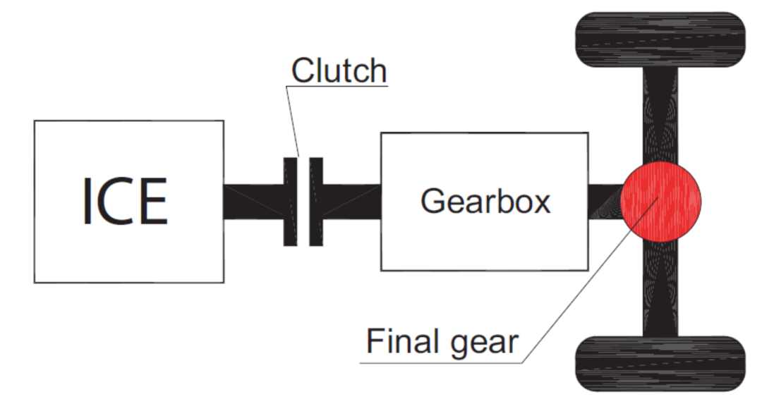
This means that for each gear the ICE has to follow the road load with both the torque and speed. Because of the small maximum efficiency region of a combustion engine, the operation is rarely at the maximum point; this gives a low efficiency of the complete drive train particularly in urban traffic.
The optimum efficiency is about 30-40% and can only be obtained in a small speed-torque region. The mean efficiency is much lower because of the small maximum efficiency region. To operate a combustion engine at optimum efficiency during all driving conditions, full control of the torque and speed is required. In a series hybrid vehicle such control is achieved but the electric machines must be dimensioned for the maximum power and all energy has to be converted from mechanical to electric and back to mechanical with losses at every conversion stage. The parallel hybrid vehicle has a smaller electric motor that is mechanically connected to the gears, which limits the control of the internal combustion engine (ICE) to only the torque. In the novel four-quadrant transducer (4QT) concept, which is a further development of the work on the integrated energy transducer, the advantages of the series and parallel hybrid systems are combined. This gives possibilities to operate the ICE independent of the road load.
A number of different hybrid and electric drivetrain systems are used worldwide; some of which are:
-
Series hybrid
The series hybrid system consists of an ICE, a generator, two inverters, energy storage (for example a battery or capacitors) and a traction motor -
Parallel Hybrid
The ICE is mechanically connected to the gearbox and thus to the wheels; this gives the possibility to control the torque but not the speed of the ICE independent of the road load. -
Integrated Starter Generator
The electric machine is small and only operates as a starter, generator and to boost the torque during acceleration. It is also possible to use the electric motor for regenerative braking. -
Integrated Energy Transducer
In the integrated energy transducer system, the ICE is connected to a double rotor machine that changes the speed to the optimal speed of the ICE while the torque is controlled with a continuous variable transmission. -
Fuel cell vehicles
The FC is more efficient than the ICE. As a comparison the tank to wheel efficiency of a FC-vehicle is almost 50%, whereas the same efficiency for an ICE vehicle is about 15%. -
Electric vehicles
The electric vehicle (EV), has an electric machine that operates mostly as a traction motor but in some cases as a generator when utilizing regenerative braking. The efficiency of the battery drive is higher than for a combustion engine, but if one for example assumes that the combustion engine drive has an efficiency of 20% and the battery drive 100%, the battery still has to be 16times heavier than the gasoline tank. In a conventional car the fuel tank is about 50litres which is approximately 37kg of fuel. A Li-ion battery then has to be 16 times heavier, i.e. 590kg to have the same driving range as a conventional car with a 50litre fuel tank. This is for a conventional car that weighs about 1500kg. If one then adds 590kg of battery, the weight and consequently the energy consumption of the car will increase. Another aspect is the charging of the battery. To fuel 50litres of gasoline takes some minutes whereas to fully charge a battery of 590kg requires 307MJ of energy, which means that a power of 1MW would be required to fully charge the battery in 5minutes.
The 4QT system consists of one ICE, two inverters, a battery and the four-quadrant transducer (4QT) which includes the slip-rings.
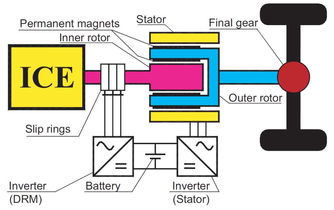
The 4QT transducer is an electric machine made up of two combined electric machines, in this case radial flux permanent magnet synchronous machines. The 4QT consists of one double rotor machine (DRM) and one conventional machine (Stator). The 4QT can replace the gearbox, clutch, and the flywheel in the vehicle but instead it needs a battery, two inverters and some control equipment. The DRM consists of the inner rotor with windings fed through the slip-rings and the outer rotor with magnets.
The Stator is a conventional stator with windings that interacts with the outer rotor of the DRM. The magnets on the outer rotor are separated into one inner layer for the DRM and one outer layer for the Stator.
Both machines are supposed to work both as motors and as generators. The 4QT is mounted between the combustion engine and the final gear in a hybrid electric vehicle. The function of the 4QT system is to keep the operation of the ICE at maximum efficiency during all driving conditions to minimize fuel consumption. The 4QT changes both the speed and torque produced by the ICE at the optimal operation point to the required speed and torque at the final gear. The DRM either increases or decreases the speed from the ICE to the speed required at the final gear. The Stator increases or decreases the torque produced by the ICE to match the demanded torque at the final gear. This enables operation at maximum efficiency and/or minimum emission of the ICE at all speeds and loads of the vehicle. It is also possible to drive the 4QT-equipped vehicle in a pure electric mode.
During this mode the driving range is then limited by the energy content of the battery. If the battery is removed the 4QT system can be operated as an electrical variable transmission system.
The 4QT system that has been investigated with the help of simulations, showed a decrease of the fuel consumption of a twelve ton vehicle by 30%. This decrease is due to the more efficient use of the ICE and the use of regenerative braking.
As shown below, the ICE efficiency is highest at high torques and at mid range speeds (2000-3000rpm) for this specific diesel engine. The optimal operation line (OOL) is the operation line where the ICE operates at optimal efficiency for a required power, and it is almost the same as the maximum torque limit for all speeds. The maximum torque and the OOL are shown below as a solid line for the maximum torque and a dotted line for the OOL. The OOL is used to obtain the maximum efficiency of the ICE.
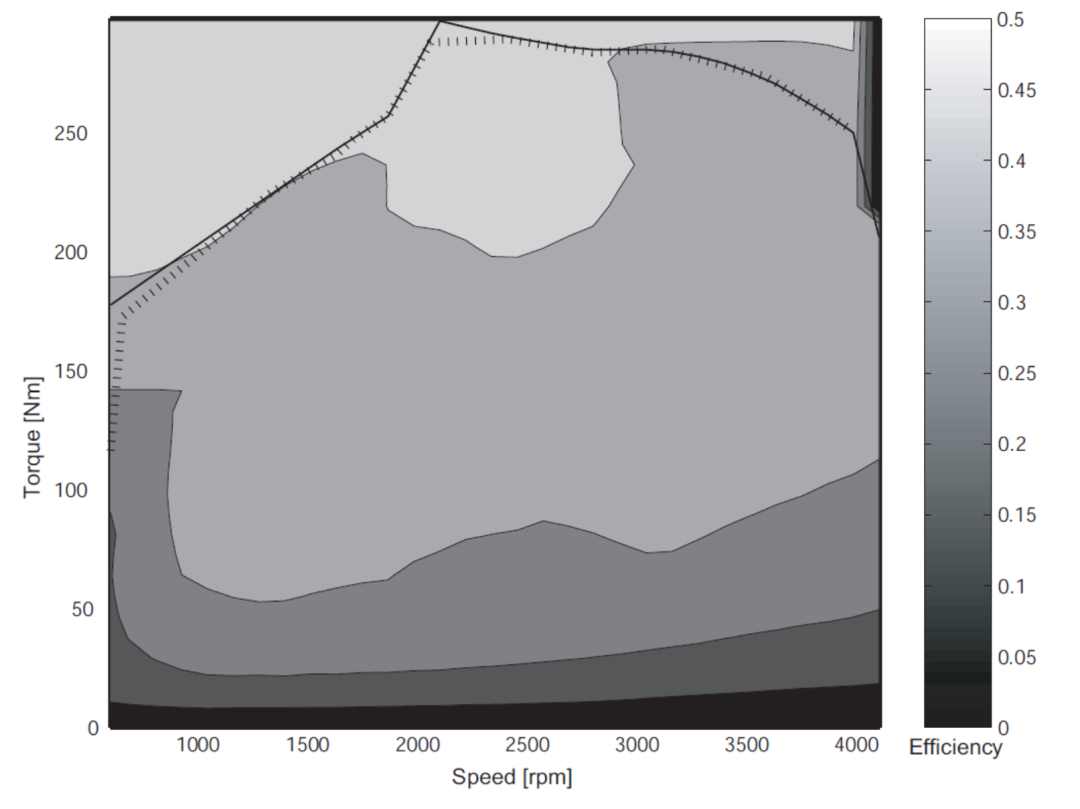
To keep the ICE operation along the OOL the 4QT changes the speed and torque required at the final gear to the speed and torque along the OOL for the ICE. The required speed and torque at the final gear can be higher or lower than the OOL.
The 4QT prototype design
A scaled down prototype has been built for a smaller vehicle application as a proof of the concept. The machine data for the prototype was achieved from simulations performed who derived the basic performance requirements of the 4QT system for a medium sized passenger car with a total power of approximately 60kW. During these simulation a combustion engine with the following parameters was used:
- 79kW maximum power at 5750rpm
- Maximum speed 6000rpm
- Maximum transient torque 148Nm at 3750rpm
- Maximum continuous torque 100Nm
- Torque at 1500rpm: 125Nm
- Torque at 6000rpm: 125Nm
Using the data above, the following performance was derived for the DRM:
- TDRM-rated = 100Nm
- nDRM-base = 3000rpm
- PDRM = 31.4kW And for the stator:
- TStator-rated = 70Nm
- nStator-base = 4000rpm
- PStator = 29.3kW
The DRM maximal continuous torque is the same as the ICE continuous torque, the stator torque is derived from the extra torque contribution needed to achieve the driving demands. These values are performance data for the two machines in the 4QT.
The radial-radial 4QT machine is assumed to fit into a cylindrical volume with a diameter of 260mm and an active length of 110mm. These dimensions exclude the housing, cooling ducts and auxiliary equipment, as for example the slip-rings.
Likewise, this is the way we built the motor configurator. You can either input your available cylindrical space and the configurator will tell you how much power our technology can deliver, or you can precise your power requirement and the configurator will automatically calculate and draw the electric motor that will fulfill your requirement. You can find out more about our electric motor configurator and create your customized electric motor within seconds if not minutes.
Pole Number
The pole number was an important factor for the motor design. Using a higher pole number reduces the endwinding length and the stator back thickness, but increases the fundamental frequency of the machine. A higher fundamental frequency gives higher iron losses and requires smaller strands in the wires to reduce the skin effect.
A side not: In our AF24PM-S axial flux light weight custom electric motor, the '24' in the model name stands for the pole number of the electric motor.
For the 4QT the most important factors that influence the choice of the pole numbers were different for the two machines. The iron losses and skin effect properties were important for both machines, as they are for most electrical machines.
For the DRM the stator back thickness is of minor importance because it is an outer rotor design and the stator back measured from the slot bottom to the shaft is normally large. The outer stator is as a conventional machine and in order to build a compact machine with a small outer radius this stator back should be kept thin.
The end winding length is more important for the DRM than for the Stator machine. This is because the rotating windings of the DRM will be vulnerable to centrifugal forces, and the length of the DRM end windings will also have a large impact on the total machine length since it is inside the outer rotor.
Using the same pole number for the DRM and the Stator reduces the outer rotor thickness; because, the no-load flux only penetrates straight through the outer rotor in radial direction and a small no-load flux is leaking between the poles in the outer rotor.
For the 4QT machine a high pole number that reduces the end winding length was preferred in order to reduce the copper losses and to minimize the effects of centrifugal forces on the end windings.