
Up to 50% Lighter: Custom Axial Flux Electric Motors
By Marius Blumenberg · Reviewed
In every mobile application, from drones to wheelchairs to robot joints, weight is paid for twice: once when the motor is built, and again every time it has to be lifted, accelerated or carried. For a custom axial flux electric motor, the torque per gram of the motor's active parts is what matters: the magnets, copper, and back-iron where present that actually produce the torque, not the peak power on a datasheet.
The axial flux topology starts ahead on torque per gram because of its geometry. PCB and DCB stators take it further: they turn the stator into a thin, rigid, structural disc that can be built without a housing, a naked motor, or run directly in a fluid, a wet motor. This is how Turncircles motors reach up to 50% weight reduction compared with conventional motors.
Configure your motor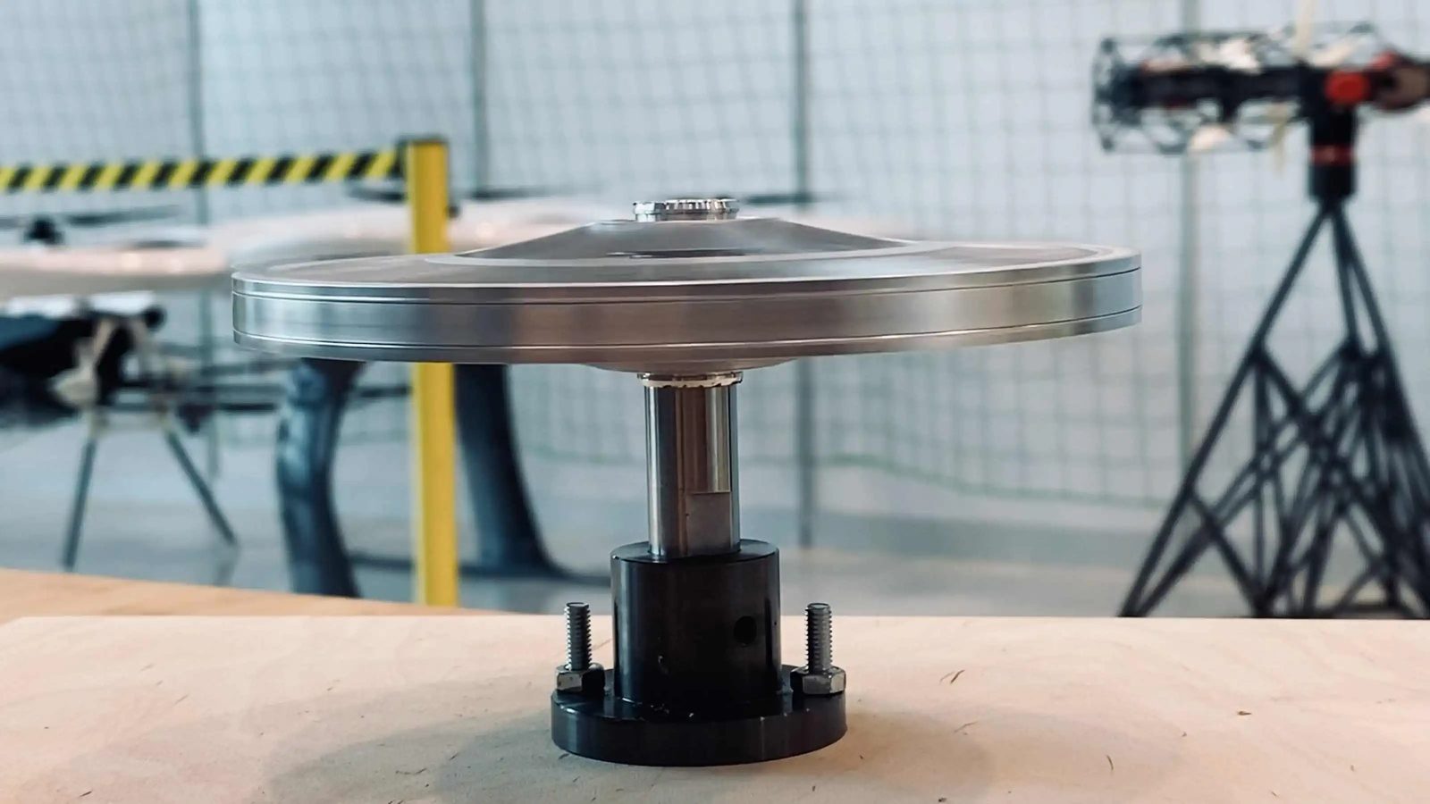
Why Axial Flux Delivers More Torque per Gram
Torque is the magnetic shear force acting on the air-gap surface, multiplied by the radius at which it acts. What differs between topologies is the shape of that surface. In a radial flux motor the air gap is a cylinder of diameter D and length L. In an axial flux motor it is a flat annulus between an inner and an outer radius. With the same magnetic shear stress S in the gap, and k a constant, the two scale differently:
Radial flux
T = k · S · D2 · L
Torque scales with the square of the diameter and with the length. Both make the motor bigger and heavier.
Axial flux
T = k · S · (ro3 - ri3)
Torque scales with the cube of the radius, where ro and ri are the outer and inner radius of the air gap. The motor stays a short disc.
Doubling the diameter multiplies the torque of a radial flux motor of fixed length by four, and that of an axial flux motor by eight. More importantly for weight, the active material of an axial flux motor, the magnets and the copper, sits at a large radius where every gram produces the most torque, and the whole motor is a short disc instead of a long cylinder.
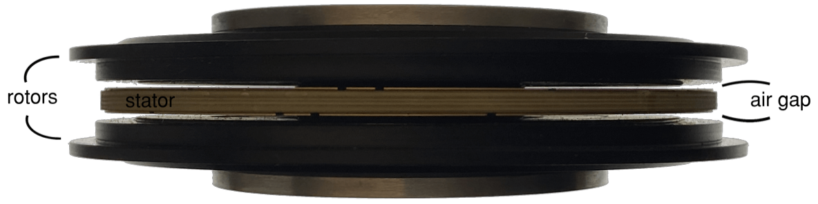
A coreless stator goes one step further. Without an iron core there are no laminations, no slots and no core losses, and the heaviest stator component disappears. Removing the core also removes cogging, since there's no ferrous material for the magnets to detent against. What remains is copper conductors between two magnet discs, a construction that suits a thin, flat, printed stator perfectly. See the full engineering trade-offs of going coreless for what this costs as well as what it saves.
Where the Rest of the Mass Goes
A motor can be excellent in its active material and still be heavy, because of the structure around it. In a conventional motor that structure typically includes:
- the housing and end bells that carry the loads and enclose the motor,
- the shaft and the bearing seats,
- the stator core and its slot insulation, bobbins and winding overhang,
- seals and fasteners, and often a cooling jacket or fins.
In small and medium motors this passive mass can rival the mass of the magnets and copper that actually make torque. Reducing it is as valuable as improving the active parts, and this is where PCB and DCB stators change the design.
PCB and DCB Stators: The Stator Becomes the Structure
In a printed stator the winding is not wound but manufactured: copper conductors are formed on a flat substrate. The geometry is repeatable, only a few millimetres thick, and has no bobbins and no end-winding overhang. Trace width, copper thickness and the number of layers are chosen to match the voltage and current of the application. Because the substrate is a rigid plate with mounting holes, the stator is also a structural part that can be bolted directly into the host design.
There are two main routes. A PCB stator uses copper on a multilayer laminate. A DCB (direct copper bonded) stator bonds thick copper directly to a ceramic such as alumina or aluminium nitride. The ceramic conducts heat far better than a laminate and tolerates higher temperatures, so the heat leaves the copper through a thin insulating layer straight into a heat sink, a structure or a fluid. A higher continuous current density means more continuous torque from the same mass. See the PCB and DCB stator windings definition for the substrate comparison and design trade-offs in full.
| Property | PCB stator | DCB stator |
|---|---|---|
| Construction | Copper traces on a multilayer laminate | Thick copper bonded to a ceramic substrate |
| Heat path | Good, limited by the laminate | Excellent, through the ceramic |
| Well suited to | Lightest designs, multi-layer windings, cost-effective series | High continuous power density, fluid or heat-sink cooling, high temperature |
| Consider | Laminate limits temperature and heat conduction | Ceramic is more brittle and costly; thick copper limits fine geometry |
Typical characteristics; the right choice depends on the thermal duty and the environment of your application.
Naked Motors: Rotor and Stator, No Housing
A naked motor is delivered as its active parts only: the magnet rotor discs and the printed stator. There is no housing, no end bells and no bearings of its own. The stator is mounted directly into the structure of the machine, such as a drone arm, a wheel rim or a robot joint, and the rotor turns on the application's own bearings.
Everything that was housing becomes part of something that was needed anyway, so the mass, the axial length and the number of parts all go down. The trade-off is that the application takes over three jobs: it supports the rotor on its bearings, it holds the axial alignment that defines the air gap, and it protects the motor from dust and moisture where needed. That is why a naked motor is designed together with the host structure, not selected from a catalogue.
Wet Motors: Let the Fluid Carry the Heat
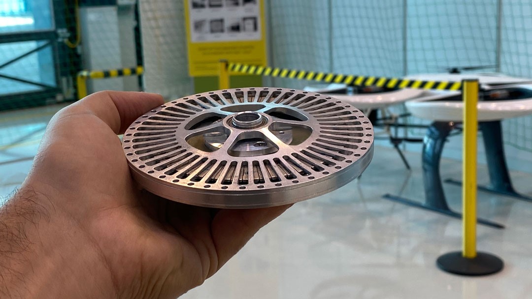
A wet motor runs immersed in a fluid, such as oil, a coolant or the process fluid of a pump. The fluid touches the stator directly, so heat is removed at its source instead of travelling through winding, potting and housing. A coreless printed stator suits this well: it has no iron laminations to corrode or soak up fluid, it is a flat insulated plate with a large surface, and a DCB ceramic passes heat into the fluid particularly well.
The weight benefit comes twice. Better cooling allows a higher continuous rating from the same mass, and the enclosure is the housing of the system, for example the pump or the gearbox, so no separate motor housing, sealing or cooling jacket is needed. As in a naked motor, the application takes on part of the job, and a wet design has its own points to validate:
- Viscous drag. Fluid in the air gap causes shear losses; the gap and the fluid viscosity are chosen together.
- Material compatibility. Conductor insulation, coatings and magnets must tolerate the fluid over the lifetime.
- Electrical insulation. The fluid must be dielectric, or the conductors fully insulated, for the operating voltage.
This is the same principle behind a canned motor pump, where the stator is sealed behind a thin can and the rotor runs directly in the pumped fluid. See our canned motor vs sealed motor guide for how sealing strategy trades off against IP rating and lifespan.
Mass Budget at a Glance
The table shows which mass items each construction carries, and which ones are removed outright or handed off to the host system instead.
| Mass item | Conventional radial, housed | Axial coreless, housed | Naked | Wet |
|---|---|---|---|---|
| Stator iron core | Present | Removed | Removed | Removed |
| Bobbins and winding overhang | Present | Removed (printed winding) | Removed | Removed |
| Housing and end bells | Present | Present, lighter | Removed | System housing |
| Bearings and shaft | Present | Present | Application | Application |
| Cooling jacket or fins | Often needed | Reduced | Host structure | Fluid |
Typical constructions; the final design depends on your application.
Weight Is an Application Requirement, So the Motor Has to Be Custom
A naked or wet motor only saves weight when it is matched to its host: the diameter to the structure, the air gap to the bearings, the printed winding to the supply voltage, the substrate to the way heat leaves. That is the same principle that applies to efficiency, as explained in custom electric motor design: only a motor designed for the exact application delivers at application level. For the topology background, see axial flux vs radial flux motors.
The Turncircles platform offers:
- up to 50% weight reduction compared with conventional motors,
- up to 96% efficiency and up to 20 years of lifetime,
- up to 24 Nm of torque per stack, stackable for more power,
- speeds up to 6000 RPM and voltages up to 370 VDC,
- up to IP67 protection for housed variants.
Configuring a motor is free. For naked or wet requirements, talk to an engineer about your structure, fluid and duty cycle.
Frequently Asked Questions
What does torque per gram mean for an electric motor?
Torque per gram, or torque density expressed per unit of mass (Nm/g), is the continuous torque a motor delivers divided by its active-part mass: magnets, copper, and back-iron where present, excluding housing and bearings. Turncircles quotes density on this basis consistently, since housing and bearings are application-dependent on a custom motor. See the full torque and power density reference guide for the complete definition.
Why does axial flux give more torque per gram than radial flux?
Torque is the magnetic shear force on the air-gap surface multiplied by the radius at which it acts. In an axial flux motor the air gap is a flat annulus and torque scales with the cube of the diameter, while in a radial flux motor of fixed length it scales with the square. The active material sits at a large radius, the motor is short, and a coreless stator removes the iron core entirely.
What is the difference between a PCB stator and a DCB stator?
Both replace a wound coil with copper conductors bonded to a flat substrate. A PCB stator uses copper traces on a multilayer laminate, which is light, flexible in geometry and cost-effective. A DCB (direct copper bonded) stator bonds copper to a ceramic such as alumina or aluminium nitride, which conducts heat much better and tolerates higher temperatures, at the cost of a more brittle, more expensive substrate.
What is a naked motor?
A naked motor is delivered as rotor and stator only, without housing, end bells or its own bearings. The stator is mounted directly into the host structure, for example a drone arm, a wheel rim or a robot joint, and the application provides bearing support and the alignment that holds the air gap. Removing the housing removes its mass, its axial length and its part count.
What is a wet motor?
A wet motor runs immersed in a fluid, such as oil or a coolant, which carries heat away directly from the stator. A coreless PCB or DCB stator has no iron laminations to corrode or hold fluid and presents a large flat surface to it. The enclosure is then the system housing, for example a pump or gearbox, so no separate motor housing or cooling jacket is needed. Viscous drag in the air gap and material compatibility with the fluid must be validated for each design.
How much lighter can a Turncircles motor be?
Turncircles axial flux motors offer up to 50% weight reduction compared with conventional motors of the same output, up to 96% efficiency and up to 20 years of lifetime. The saving depends on the application: a naked or wet configuration removes the most mass, and every motor is designed for your torque, speed, voltage and envelope.
Take weight out of your motor
Configure a custom axial flux motor in minutes, or talk to an engineer about a naked or wet design for your structure.
Configure your motor Talk to an engineer