
Why We Need Lighter Electric Motors
By Kaan Ozgen · Reviewed
Electric motors are the premise of modern propulsion, from vacuum cleaners to drones, from electric bikes to cargo aircraft. Making them lighter and more efficient is the enabling step that determines what the application can actually do, far beyond an incremental tweak. Aerospace companies invest an average of €50 per gram saved, because every gram removed from a motor is a gram that can fly longer, carry more, or charge less often.
At Turncircles we build coreless axial flux permanent magnet BLDC motors that deliver more torque per gram than any conventional motor topology, without sacrificing efficiency or reliability.
Because electric motors are predominantly made of metal (copper windings, iron laminations, steel shafts, aluminium housings), they are naturally heavy, especially as power ratings increase. This extra weight creates a compounding problem: a heavier motor requires more energy to move itself, which requires a larger battery, which adds more weight, which requires still more power. Reducing motor mass through better design is the only way out of that cycle.

What is an Electric Motor?
An electric motor is an energy converter: it transforms electrical current into mechanical rotation by exploiting the interaction between magnetic fields and current-carrying conductors. The same physical principle works in reverse: a generator converts mechanical rotation into electrical current. In both cases the underlying law is electromagnetic induction: a changing magnetic field induces an electromotive force, and a current in a conductor within a magnetic field experiences a mechanical force.
Every electric motor has two structural parts: the stator (the stationary part) and the rotor (the rotating part). The stator carries windings or permanent magnets that establish a magnetic field; the rotor is attracted and repelled by that field in a controlled sequence, producing continuous rotation. The efficiency of this conversion, and the weight required to achieve a given torque, depends on the motor's geometry, materials, and magnetic circuit design.
Radial Flux vs. Axial Flux: The Geometry That Defines Weight
The most fundamental design choice in a brushless motor is the direction of the magnetic flux relative to the rotation axis.
In a radial flux motor (the conventional outrunner or inrunner design used in most commercial products), the magnetic flux travels radially, from the centre of the motor outward (or inward). The stator is a cylindrical iron core with slots cut into it to hold the copper windings, and the rotor surrounds (or sits inside) this core. The iron is essential: without it, the magnetic reluctance of the air gap would be too high and the torque density would collapse. But iron is heavy, and it introduces core losses (hysteresis and eddy current losses) that are present at all operating speeds.
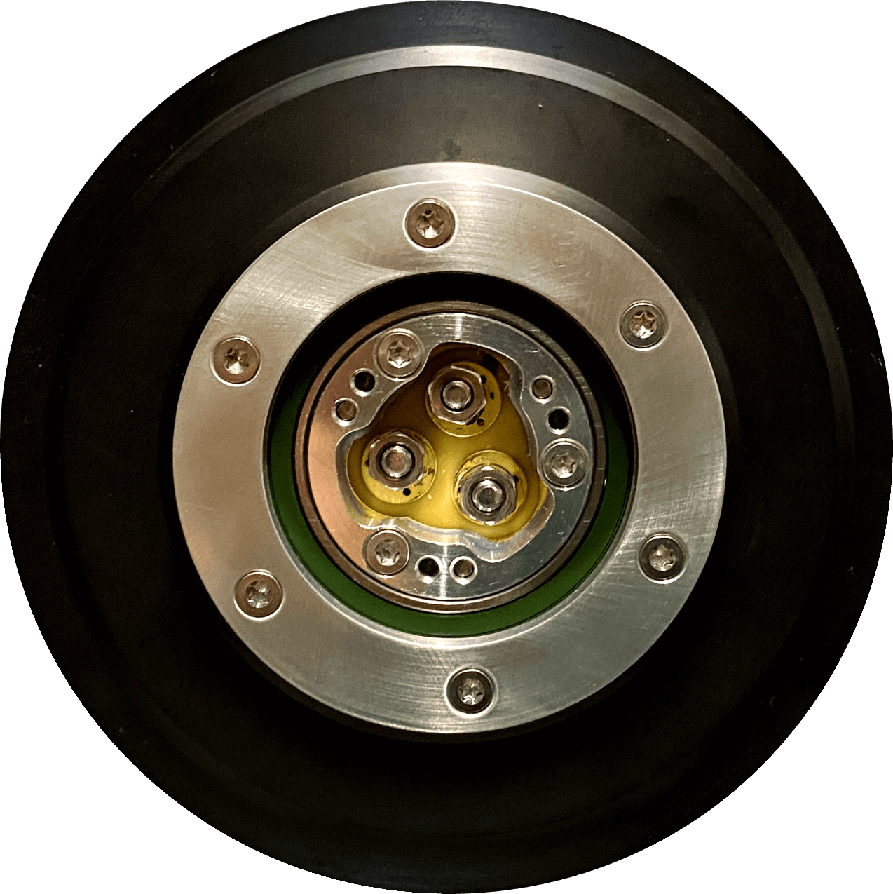
In an axial flux motor, the magnetic flux travels parallel to the rotation axis: axially, through a flat disc-shaped air gap. The rotor and stator face each other across this axial gap rather than wrapping around each other. This geometry is more compact in the axial direction, producing the characteristic flat "pancake" shape. It also enables a coreless stator design that is impossible in radial flux motors. See our full axial flux vs. radial flux motors comparison for a deeper breakdown of power density, thermal behaviour, and application fit.
Types of Electric Motors
-
Brushed DC Motors
The oldest and simplest design. Carbon brushes maintain sliding electrical contact with a rotating commutator, alternating the current direction in the rotor windings to sustain rotation. Brushes wear out, limit maximum RPM, and generate electrical noise. Almost entirely superseded in performance applications by brushless designs.
-
Brushless DC Motors (BLDC)
The brushes and commutator are replaced by an Electronic Speed Controller (ESC) that generates precisely timed three-phase current based on rotor position feedback. BLDC motors are more efficient, longer-lived, and capable of higher power densities than brushed equivalents. They are the standard for drones, electric vehicles, electric bikes, and industrial automation. Our axial flux motors are BLDC motors.
-
Asynchronous AC Induction Motors
The rotor is electromagnetically induced by the rotating magnetic field of the stator: no permanent magnets or brushes required. The rotor always lags slightly behind the stator field (the "slip"), which limits peak efficiency. Induction motors are robust and inexpensive and dominate industrial fixed-speed applications, but their efficiency and power density are lower than BLDC designs at the sizes relevant to mobile applications.
-
Permanent Magnet Synchronous Motors (PMSM)
The rotor carries permanent magnets and rotates synchronously with the stator field: no slip. Efficiency and power density are higher than induction motors. Most modern EV traction motors and high-performance servo drives are PMSMs. Axial flux permanent magnet motors are a subtype of PMSM with superior torque-to-weight characteristics.
Why Permanent Magnets?
High-performance permanent magnets are made from neodymium iron boron (NdFeB), a rare earth alloy with the highest energy product of any commercially available magnet material. Once magnetised, a neodymium magnet retains its field for decades: it loses an estimated 5% of its magnetism over 100 years under normal conditions. Permanent magnets eliminate the rotor copper losses associated with wound-field motors and allow the rotor to be made passive: no slip rings, no windings, no resistive heating in the rotor.
The challenge with permanent magnets is flux channelling. To make full use of the magnet's energy, the flux must be directed efficiently toward the stator winding rather than leaking into the surrounding structure. Engineers conventionally do this by placing a ferromagnetic backing plate behind the magnets, but iron is heavy. The Halbach array solves this without iron: by arranging magnets in a specific rotating sequence, the magnetic field is self-concentrating on one face of the array and nearly cancels on the other. This allows a coreless, ironless motor design that is both lighter and produces no cogging torque.
Why Axial Flux Maximises Torque per Gram
The force between the stator current and the rotor magnetic field produces torque in a brushless motor. That force is proportional to the product of the field strength and the current, and it is maximised when the two are perpendicular. In an axial flux motor, the interaction between the axial rotor field and the tangential stator current is perpendicular across the full disc area of the active region, a geometry that converts current to torque more efficiently than the radial geometry of a conventional motor.
The result is a higher torque constant (Nm/A) per unit mass, which means a given torque requirement can be met with less copper, fewer magnets, and no iron stator core. Removing the iron core eliminates all core losses: hysteresis and eddy current losses that are otherwise present and wasteful at every operating speed. The motor runs cooler, requires less cooling mass, and maintains high efficiency across the full throttle range rather than only near its rated operating point.

The Scalable and Stackable Architecture
One of the most practical advantages of the axial flux topology is its modularity. Increasing motor diameter raises torque at constant speed; adjusting the number of winding turns changes the motor's voltage and current characteristics; and, uniquely to axial flux, additional rotor-stator pairs can be stacked axially on the same shaft to multiply power output without increasing the motor's footprint. Two stacks doubles the power; three stacks triples it.
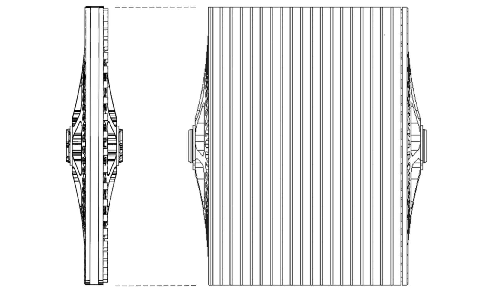
This stackable architecture means a single motor platform can address a wide range of power requirements by varying the number of stacks. A UAV motor producing 300 W as a single stack becomes a 900 W motor for a cargo drone as a three-stack, using the same tooling, the same windings, and the same magnet sets. That cuts development cost, certification scope, and supply chain complexity.

Applications Where Motor Weight is Mission-Critical
The weight compounding problem (heavier motors demand more energy, which requires heavier batteries) is most acute in applications where the motor is airborne or the system is energy-constrained. These include:
-
Drones and UAVs
Motor weight determines hover endurance and payload capacity. On a quadcopter, saving 100 g per motor saves 400 g total, enough for a thermal camera, extra battery, or longer mission endurance. See our article on long-flight UAV drones with thermal cameras.
-
Electric Vertical Take-Off and Landing (eVTOL)
Urban air mobility vehicles must carry passengers under tight weight and energy budgets. Reducing propulsion system mass enables longer range, higher payload, or smaller battery packs, all commercially critical parameters.
-
Electric Bikes and Light Mobility
A mid-drive or hub motor that is 200 g lighter improves handling, reduces unsprung mass, and extends range on a given battery capacity. In competitive cycling and performance e-bikes, motor weight is a primary design criterion.
-
Robotics and Exoskeletons
Actuators in robotic arms and wearable exoskeletons are carried by the very structure they drive. Lighter motors reduce the cumulative load on proximal joints, enabling longer operation and more natural movement dynamics.
-
Aerospace and Space
In satellite attitude control, rocket thrust vector control, and space robotics, motor mass is costed at launch price, typically thousands of euros per kilogram. The €50/gram aerospace investment benchmark cited at the start of this article understates the actual cost in space applications.
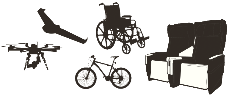
Across these applications, the motor must carry itself before it can do useful work. Because weight compounds in energy-constrained systems, a motor that is 40% lighter delivers more than a 40% improvement in capability. That is why lighter electric motors matter, and why advancing the state of the art in motor topology sits at the core of what Turncircles does.
Explore Custom Axial Flux Motors
Custom High-Efficiency Electric Motor Design
Why only a motor designed around the exact application delivers efficiency at application level.
Lightweight Axial Flux Electric Motors
Torque per gram, PCB and DCB stators, and naked or wet motors that save housing weight.
Axial Flux vs Radial Flux Motors
An engineering comparison of the two topologies: power density, thermal behaviour and application fit.
Application Concepts
Concept studies for drones, VTOL cargo aircraft and space vehicles built around axial flux motors.
Design your axial flux motor
Use the Turncircles configurator to set your torque, speed, and power requirements and get a simulation-backed motor specification, in minutes.
Configure your motor