
Electric Motor Torque Density and Power Density: The Reference Guide
By Kaan Ozgen · Reviewed
Electric motor torque density (Nm/kg) and motor power density (kW/kg) are the two figures behind almost every "torque per gram" and "power-to-weight ratio" claim on this site and across the industry, including ours. This guide defines both metrics precisely, shows why most published density figures can't be compared to each other, and states the exact basis Turncircles uses so our own numbers are checkable.
Most density claims aren't wrong. They're just silent about what they're measured against. A figure that doesn't say whether it's peak or continuous, or whether the mass includes housing and bearings or just the active electromagnetic parts, isn't comparable to anything. Active-part mass is a legitimate basis when it's declared. The issue is the silence, not the choice.
Table of contents
- 1. What torque density and power density mean
- 2. Why density is the metric that matters
- 3. Torque density vs power density
- 4. How to read a density figure
- 5. Where torque comes from: air-gap shear stress
- 6. Why axial flux wins on torque density
- 7. The thermal ceiling
- 8. Mass: where the kilograms actually go
- 9. Removing iron: the coreless contribution
- 10. Dual-rotor and multi-disc stacking
- 11. Motor constant and efficiency
- 12. How to compare motors fairly
- 13. How Turncircles quotes density
- 14. Frequently asked questions
1. What Torque Density and Power Density Mean
Neither metric is a property of a motor topology in the abstract; both are properties of a specific design, at a specific size, built with specific materials, measured against a specific basis. That last part, the basis, is what most published figures leave out, and it's the subject of most of the rest of this page.
Torque density is torque divided by a reference mass or volume: Nm/kg gravimetrically, Nm/L volumetrically. Power density is the same idea for power: kW/kg or kW/L. Both are the site's own long-standing shorthand, "torque per gram" and "power-to-weight ratio," made precise enough to actually compare.
The everyday analogy is strength-to-weight versus speed-to-weight. Torque density is how much turning force a strong-for-its-size motor delivers per kilogram; power density is how much shaft power a fast-for-its-size motor delivers per kilogram, at whatever speed it happens to run. A motor can be excellent on one and unremarkable on the other, and which one matters depends entirely on what the motor has to do.
Both figures come in gravimetric and volumetric form, and the two don't always favour the same design. A motor optimised purely for Nm/kg wants mass out of the design wherever it doesn't contribute torque; a motor optimised purely for Nm/L wants the active material packed as tightly as the thermal design allows, even if that costs some mass elsewhere. Most real designs sit somewhere between the two, because both the vehicle's weight budget and its available envelope are usually fixed at the same time, not traded off against each other freely.
Which basis dominates the decision depends on what's actually constrained. A quadcopter arm cares about gravimetric density first. Every gram not spent on the motor is a gram available elsewhere on the airframe, and there's usually room to make the motor slightly larger if it stays light. A robot joint or an in-wheel drive is often the opposite: the envelope is fixed by the mechanical design around it, so volumetric density decides whether the motor fits at all, and mass is the secondary concern once it does.
2. Why Density Is the Metric That Matters
Motor mass doesn't stay contained to the motor. A lighter motor needs a lighter mount and a lighter structure around it; in a mobile system it needs a smaller battery to move the same total mass the same distance, which is itself lighter, which needs a slightly smaller structure again. Mass compounds through the whole system in both directions: added weight and removed weight both multiply rather than simply add.
This compounding is strongest exactly where torque and power density claims are most common: drones and other aircraft, where every gram not spent on the motor is a gram available for payload, battery, or flight time; legged and articulated robots, where motor mass sits on the far end of a limb and directly increases the inertia every joint upstream has to accelerate and decelerate; and electric vehicles, where motor mass is unsprung or semi-sprung weight that affects both range and ride. See how this plays out concretely for a lightweight axial flux electric motor built specifically around torque per gram.
A high power-to-weight ratio electric motor doesn't only improve the motor. It changes what the rest of the system is allowed to look like.
The compounding argument holds even outside mobile applications, in a quieter form. A fixed installation doesn't pay a range or battery penalty for extra motor mass, but it still pays for it in shipping, in the crane or hoist needed to install it, in the structure it has to be bolted to, and in every subsequent handling step over the equipment's service life. Density is a mobility metric first, but it's rarely irrelevant even when nothing is expected to move.
What makes density worth optimising for, rather than just a number to quote, is that it's usually one of the cheapest levers available at the system level. Squeezing another few percent of efficiency out of a converter or drivetrain is often diminishing-returns work measured in engineering-months; choosing a fundamentally denser motor topology can remove a comparable fraction of system mass in one decision, before any detailed optimisation work even starts.
3. Torque Density vs Power Density
This is the single most common confusion in torque and power density search results, so it's worth stating precisely, early, and in terms of the one equation that governs it:
P = T · ω
Power equals torque times angular speed. Because speed is a free variable in that equation and mass isn't tied to it the same way, power density rises with speed while torque density does not. A small, fast, geared motor and a larger, slower, direct-drive motor can be specified to produce exactly the same kW/kg, and still differ several-fold in Nm/kg, because the geared motor reaches its power target mostly through speed, and the direct-drive motor reaches the same power mostly through torque, at a fraction of the RPM.
Which figure to optimise for depends on where the gearbox lives, not on which number looks better. If a gearbox is already part of the design, power density is the more honest comparison, because the gearbox will convert the motor's speed into whatever torque the application actually needs. If the application is direct-drive (no gearbox between motor and load), torque density is what determines whether the motor can do the job at all, because there's no downstream stage left to make up a torque shortfall. The direct-drive-vs-geared-motor question should be answered before either density figure is used to compare two motors.
This is also why a "highest power density" claim can be true and still be the wrong motor for a direct-drive application. A high-speed, low-torque motor paired with an external gearbox can post an excellent kW/kg figure on the motor alone, while the gearbox, which the density figure doesn't include, adds mass, mechanical losses, backlash, and a wear item that the motor's own datasheet says nothing about. The system-level density, motor plus gearbox together, is what a direct-drive design is implicitly being compared against, even when only the motor's number is quoted.
4. How to Read a Density Figure
Every Nm/kg or kW/kg number hides four choices. Change any one of them and the number changes, often by a large factor, without the motor itself changing at all. None of the four choices is dishonest by itself. Every one of them is a legitimate basis used somewhere in the industry. The problem is comparing two figures that were computed on different choices without realising it, which happens constantly because most published specifications simply don't say which choice was made.
| Choice | Option A | Option B | Effect |
|---|---|---|---|
| Torque or power condition | Continuous | Peak | Peak is always higher, sometimes several-fold, and meaningless without a stated duration |
| Mass basis | Active parts (magnets, copper, back-iron) | Complete motor (+ housing, bearings, shaft) | Active-mass figures read higher; complete-motor figures include overhead the design doesn't control on a custom build |
| Volume basis | Active volume | Outer envelope (incl. shaft, connectors) | Envelope figures are the more useful ones for a packaging decision; active-volume figures read higher |
| Speed the power figure is quoted at (power density only) | Rated speed | Maximum speed | A power figure quoted at maximum speed is not the power available continuously at the rated operating point |
Nm/kg motor specifications and kW/kg electric motor specifications should always be read as answers to "on which basis" before they're compared to another datasheet. To calculate motor torque density for a fair comparison, restate every figure you're comparing on the same four choices first: recompute if the manufacturer states enough detail to do so, and discard the comparison if they don't.
The commercial incentive runs entirely one way here: quoting the basis that produces the largest number costs a manufacturer nothing and reads better on a datasheet, while quoting the most conservative basis looks worse next to a competitor who didn't. That asymmetry is why an undeclared basis is worth treating as a red flag rather than an oversight. It's rarely accidental, and the honest fix is simply to ask, in writing, what the figure is measured against before using it in any real comparison or design decision.
5. Where Torque Comes From: Air-Gap Shear Stress
Every density figure ultimately traces back to one physical quantity: the tangential force per unit area developed at the air gap, called shear stress and measured in kPa. Shear stress is the product of electric loading (how much current-carrying copper surface faces the gap) and magnetic loading (how strong the field crossing the gap is). It's the same quantity in every motor topology. What differs between designs is how much rotor surface area that shear stress gets to act over, and at what radius.
For a cylindrical rotor, torque is approximately shear stress multiplied by the rotor's surface area multiplied by its radius, a surface that scales with radius times axial length and acts at that same radius. That means every improvement in torque density is, underneath, one of exactly three things: a higher achievable shear stress (better magnets, thinner effective air gap, better cooling to allow more current), more rotor surface area for the same mass, or that surface area sitting at a larger radius for the same mass. There is no fourth lever. Section 6 shows how axial flux geometry pulls on the third one particularly hard.
Electric loading and magnetic loading are each bounded by something physical, not by design ambition. Electric loading is set by how much current-carrying copper can be packed along the gap and how much current density that copper can sustain without overheating: the same thermal-ceiling argument covered in section 7, arriving from a different direction. Magnetic loading is set by magnet grade, magnet thickness, and how effectively the magnetic circuit concentrates flux across the gap, which is where the coreless-vs-iron-core choice in section 9 has its electromagnetic effect. Shear stress is where those two independently-bounded quantities meet, making it the single number worth tracking across very different motor designs.
6. Why Axial Flux Motor Torque Density Wins
In an axial flux motor, the active surface is a disc annulus rather than a cylinder wall, and at uniform shear stress the torque produced by one disc face is:
T = 2π⁄3 · σ · (Ro3 − Ri3)
Torque rises with the cube of the outer radius, not the square. Doubling a radial motor's diameter (at fixed length) roughly quadruples its torque; doubling an axial flux motor's diameter roughly multiplies its torque by eight. This is the geometric argument for axial flux in any envelope that's short and wide rather than long and narrow: the active material sits at a large mean radius, and the motor itself stays a thin disc instead of a long cylinder, so very little mass is spent getting material away from the axis where it does the least work.
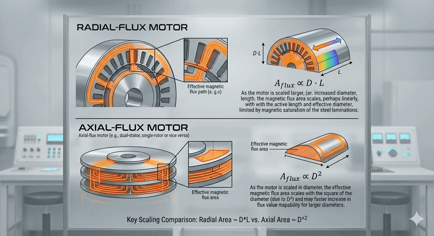
The inner radius matters too: a disc with too small an inner radius wastes area near the centre, where the radius term contributes little to torque but the copper still has to turn the corner through the end windings, adding resistive loss without adding much torque. Optimisation studies on axial flux geometry generally put the best inner-to-outer radius ratio somewhere around 0.5 to 0.7 depending on exactly what's being optimised, with a widely cited analytical result for pure torque maximisation of 1/√3 (≈ 0.577) (Gieras, Wang & Kamper, Axial Flux Permanent Magnet Brushless Machines, 2nd ed., Springer, 2008); the practical optimum for a specific design also depends on winding and cooling constraints, not the torque equation alone.
"Large mean radius" is doing more work in that argument than it might first appear. It's not simply that a bigger motor produces more torque. Any motor produces more torque if you make it bigger. The point is that for a fixed amount of active mass, axial flux geometry lets you spend that mass further from the axis, where the torque arm is longer and every gram of magnet or copper contributes more turning force. A radial motor of fixed length can't move its active material outward without also growing its cylindrical volume roughly in proportion; an axial disc can grow its diameter while barely changing its axial footprint.
The advantage shrinks in two situations: at small diameters, where the cube-law advantage has little radius to work with and manufacturing tolerances matter proportionally more; and in long, narrow envelopes, where a radial flux motor can use the available length directly while an axial flux motor has to stack multiple thin discs to use the same envelope efficiently (see section 10). Large-diameter discs also raise their own manufacturing questions: flatness tolerance across the disc face, and rotor stiffness against the axial magnetic attraction between rotor and stator. Neither problem scales away for free just because the torque equation says bigger is better. See the full axial flux vs radial flux motors comparison for where each topology is the better fit.
7. The Thermal Ceiling: Continuous vs Peak Torque Density
Shear stress can't push arbitrarily high. It's limited by current density in the winding, and current density is limited by how fast the resulting heat can be removed before the winding's temperature exceeds what the insulation and magnets can tolerate. Continuous density is, in other words, fundamentally a heat-removal problem rather than an electromagnetic one: the electromagnetics would happily sustain much higher shear stress if the heat had somewhere to go.
This is why cooling method changes the achievable continuous density directly, and changes the ratio between continuous and peak density along with it. A motor that can only shed heat by natural convection has a low continuous ceiling and a large gap to its peak capability, because peak operation only has to be sustained for the short time it takes the windings to heat up, not indefinitely. Better cooling (forced air, a liquid jacket, or direct fluid contact) raises the continuous ceiling toward the peak, narrowing that gap.
This is also why a peak torque or power density figure, quoted without a duration, tells you almost nothing. Every motor can produce a large peak for a short enough pulse, because the winding's thermal mass absorbs the heat faster than it can raise the temperature meaningfully. What differs between motors is how long that peak can be sustained before the continuous ceiling is the only thing left standing, and that duration is the number that actually belongs next to any peak figure.
Cooling method sets where the continuous ceiling sits, roughly in this order from lowest to highest achievable continuous density: natural convection, where heat leaves only through still air and the housing's own surface area; forced-air cooling, where a fan multiplies the effective heat transfer coefficient at the housing surface; liquid cooling, where a jacket or channel removes heat close to its source rather than waiting for it to conduct out to the housing; and direct immersion or wet-rotor construction, where the coolant contacts the winding or stator directly with no intervening housing wall at all. Each step generally narrows the gap between continuous and peak density, because each one raises how much continuous shear stress the thermal design can actually sustain, without changing what the electromagnetics could theoretically produce for a brief pulse.
This is precisely the trade the sealed motor thermal design decision makes explicit: a sealed motor's heat has to cross a boundary it wouldn't otherwise have, which typically lowers its continuous ceiling relative to an unsealed design with the same active parts, while a canned motor's rotor and stator can sit in direct contact with a coolant, at the cost of the can losses and lifespan trade-offs covered there.
8. Mass: Where the Kilograms Actually Go
A motor's total mass splits into parts that scale with torque output and parts that are largely overhead: mass the design carries regardless of how much torque it produces. Knowing which is which is what makes the active-vs-complete mass basis in section 4 more than an accounting choice.
| Component | Scales with torque? |
|---|---|
| Magnets | Yes (active part) |
| Copper (winding) | Yes (active part) |
| Back-iron (if used) | Partially (active part, but contributes no torque itself) |
| Structure / rotor discs | Indirectly (must carry the magnetic and mechanical loads torque implies) |
| Housing, bearings, shaft | No (overhead, largely application-dependent) |
| Cooling hardware (if any) | No (overhead, tied to continuous rating, not torque directly) |
Magnets and copper are what produce torque, so their mass is genuinely active. Back-iron is a special case, covered fully in section 9: it's usually counted as an active part, but it doesn't itself produce torque. It exists to concentrate flux and could, in principle, be removed entirely.
This is why "active-part mass" needs its own definition, not just a declared basis: Turncircles states plainly, in section 13, precisely which line items count. A strict reading that counts only magnets, copper, and back-iron produces a smaller, more favourable mass figure than a generous reading that also folds in structural discs or a thin protective coating, so the definition has to say exactly what's inside and outside that boundary.
9. Removing Iron: The Coreless Contribution to Density
Stator iron is mass that produces no torque of its own. It concentrates flux and lowers the magnetic circuit's reluctance, which lets the magnets and copper produce more torque than they could unassisted. But the iron itself never carries current and never sees a Lorentz force. Every kilogram of it is pure overhead relative to the shear-stress argument in section 5, paid for with a compact air gap rather than with active torque-producing material.
Iron earned its place in motor design for a good reason: a low-reluctance path lets a modest magnet produce a strong field across a small air gap, which historically mattered more than it costs in mass when magnet materials were weak and expensive. Modern rare-earth magnets shift that balance. They're strong enough, in the right geometry, to bridge a larger effective gap without iron's help, which is what makes removing the iron a density gain rather than a step backward.
A coreless axial flux motor removes that mass entirely, at a cost: without iron to concentrate flux, the effective air gap grows, which demands stronger magnets (usually in a Halbach array) to reach useful shear stress, and the windings sit fully exposed to the time-varying field, which raises AC copper losses at high frequency. The density gain is real and the trade-offs are real; neither cancels the other out, which is why the full trade-off deserves its own treatment rather than a one-line summary here.
The net effect on density is still favourable for most applications this site's density claims are aimed at, because the mass removed is pure overhead relative to torque production, while the cost is paid in AC losses and magnet spend rather than in mass. A design that's thermally constrained rather than mass-constrained gets less benefit from going coreless, since removing core loss doesn't help a design that was never limited by it in the first place. It's another reminder that density gains and efficiency gains are related but distinct arguments, developed fully in section 11.
10. Dual-Rotor and Multi-Disc Axial Flux Torque Density Stacking
Where the cube-of-radius argument in section 6 runs out of room (a long, narrow envelope where growing the diameter isn't an option), axial flux motors have a second lever: stacking additional rotor-stator pairs on the same shaft. Each stage adds torque at close to linearly, because it's simply another disc doing the same job, while the shaft, bearings, and much of the housing are shared across all stages rather than duplicated.
Because the shared structure doesn't scale linearly with stage count, density per stage generally improves as stages are added, at least until the shared structure itself has to grow to carry the additional torque and axial load. A two-stack motor carries roughly one motor's overhead plus twice the active material, not the mass of two single motors bolted together.
The limit eventually shows up in the shaft and bearings rather than in the discs themselves. Each additional stage adds torque the shaft has to transmit and axial magnetic attraction the bearings have to resist, so beyond some stage count the shared structure has to grow to keep pace, and the density gain per additional stage shrinks. In practice this means stacking is the right lever specifically when the envelope is genuinely length-constrained rather than diameter-constrained. For a short, wide envelope, growing the diameter per section 6 is almost always the more mass-efficient move first.
11. Motor Constant Km and the Density-Efficiency Trade
Density figures say how hard a design is being driven, not how efficiently it converts current into torque. The honest companion metric is the motor constant:
Km = T ⁄ √Ploss
Torque per square root of resistive loss, quoted at a specific winding temperature, since copper resistance (and therefore loss for a given current) changes with it. Km is basis-independent of cooling: unlike a continuous density figure, it doesn't change if you bolt on a better heatsink, because it describes the winding's own electromagnetic efficiency at converting current into torque, not how much heat the surrounding design can carry away.
The square root isn't an arbitrary choice of exponent. Torque scales roughly linearly with current, while resistive loss scales with current squared, so torque divided by the square root of loss is the ratio that stays constant as current changes for a fixed winding design. It captures something about the winding's geometry and material, not the operating point chosen when the figure was measured. That's what makes Km comparable across motors driven at different current levels, in a way that a torque or loss figure alone isn't.
This is why two motors can share an impressive density figure and differ sharply in practice: a high-density design pushed hard on current density can have a mediocre Km, meaning it's paying for that density in efficiency and heat rather than winning it for free. Density and efficiency are related, but they're not the same trade. A motor optimised purely for density, without regard to Km, is a motor optimised to run hot.
12. How to Compare Electric Motor Specifications Fairly
A short checklist, worth applying to any datasheet or supplier conversation before a single Nm/kg or kW/kg number is trusted:
- Continuous or peak? If peak, for how long, and starting from what temperature?
- What mass is in the denominator? Active parts only, or the complete motor including housing, bearings, and shaft?
- What volume is in the denominator, for a volumetric figure? Active volume, or the outer envelope including shaft and connectors?
- For power density, at what speed? Rated speed, or maximum speed the motor can briefly reach?
- What winding temperature is assumed? Especially relevant when comparing Km or any efficiency-adjacent figure.
- What cooling is assumed? A continuous figure is only as real as the cooling path that was assumed to produce it.
If a supplier can't answer these directly, treat the density figure as marketing copy rather than an engineering spec, and ask for the basis before comparing it to anything.
A supplier who can answer all six without hesitating is also telling you something beyond the numbers themselves: that the density figure came from a design process that tracked its own basis deliberately, rather than from a marketing pass over a simulation report after the fact. That's a reasonable proxy for how much to trust the rest of the datasheet, not just the density line.
13. How Turncircles Quotes Density
Turncircles quotes torque and power density on continuous operation, active-part mass (magnets, copper, and back-iron where present, excluding housing and bearings), with peak figures always stated separately and never blended into the same number. Volumetric density is quoted against the outer envelope, since that's the figure that actually answers a packaging question.
The reasoning follows directly from how the motors are built. Turncircles designs custom motors around each application, which means housing and bearings are themselves application-dependent. A naked motor built into a drone arm and the same active electromagnetic design housed for a sealed pump application would report wildly different complete-motor density figures despite being electromagnetically identical. A complete-motor figure would be a fact about someone else's mechanical integration, not about the motor design itself. Active-part mass is the part Turncircles' design process actually targets a density figure against, so it's the only basis that stays meaningful across every application the same electromagnetic design gets built into.
Peak figures are never blended into the headline continuous number, and are always paired with the duration they were verified over, per the thermal-ceiling argument in section 7. This is the same discipline the checklist in section 12 asks any supplier to apply. The basis Turncircles commits to here is simply that checklist, answered once, in writing, rather than answered case by case when asked.
To see this basis applied to your own torque, speed, and envelope requirements, configure a motor and review the simulated density figures directly, quoted on exactly the basis described above. See the Analytical results guide for how those figures are read.
14. Frequently Asked Questions
What is torque density?
Torque density is a motor's torque divided by a reference mass or volume, usually expressed in Nm/kg (gravimetric) or Nm/L (volumetric). It is only comparable between motors when both figures use the same basis: the same torque condition (continuous or peak) and the same mass or volume definition (active parts or complete motor).
What is a good torque density for an electric motor?
There is no single good number, because "good" depends entirely on the basis the figure is quoted on and the application's duty cycle. A peak, active-mass figure and a continuous, complete-motor figure for the very same motor can differ several-fold. The useful question is not "is this number good" but "what basis is this number on, and is that the basis my application needs".
What is the difference between torque density and power density?
Power equals torque times angular speed (P = T·ω), so power density rises with speed while torque density does not. Two motors can share the same kW/kg and differ several-fold in Nm/kg if one reaches its power through higher speed rather than higher torque. Torque density is the more meaningful figure for direct-drive applications; power density matters more when a gearbox or high-speed operation is already part of the design.
Why do axial flux motors have higher torque density?
Torque in an axial flux motor acts over a disc surface, so it scales with the cube of the outer radius; in a radial flux motor of fixed length it scales with the square. The active material also sits at a larger mean radius for a given envelope, and the motor itself is short and flat rather than long and narrow, which further favours mass efficiency.
Is peak or continuous torque density the right figure to compare?
Continuous, for almost any real duty cycle comparison, because continuous density reflects what the motor's thermal design can actually sustain rather than a brief current pulse. A peak figure without a stated duration is close to meaningless. Ask how long the peak can be held before comparing it to anything.
Design to a density figure you can defend
Use the Turncircles configurator to set your torque, speed, and envelope requirements and review simulated torque and power density on the basis described above.
Configure your motor