6. Analytical Calculation Results and Indicative price
This card summarises the analytical model of your design. It updates instantly when you move any slider. Use it to check the design before you spend tokens on a simulation.
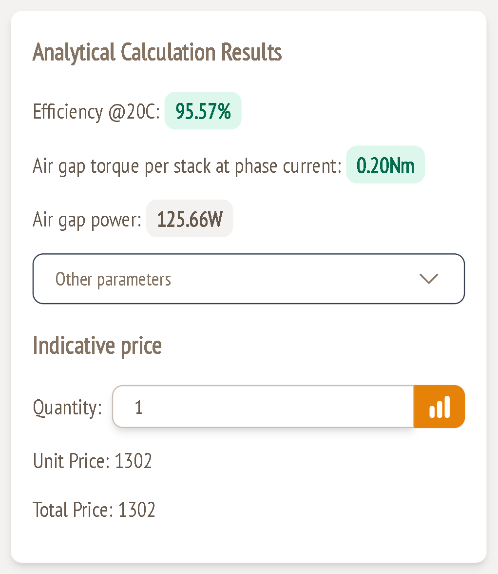
Headline results
Efficiency @20C
This is the estimated efficiency at the nominal operating point with the winding at 20 °C.
| Efficiency | Colour |
|---|---|
| 85 % or more | Green |
| 70 – 85 % | Amber |
| below 70 % | Red (configuration invalid) |
Air gap torque per stack at phase current (Nm)
This is the torque one stack produces in the air gap when it carries the phase current from the Electrical card. It must be at least the torque per stack you asked for. If it's lower, the pill turns red and you get the warning "Try increasing the number of turns."
A healthy margin covers losses and the difference between the analytical model and simulation. The example makes 0.20 Nm against 0.10 Nm required.
Air gap power (W)
This is the air gap torque × mechanical angular speed. Example: 0.20 Nm × 628.3 rad/s = 125.66 W. It shows the power capability at nominal speed and phase current, before losses.
Other parameters
Click Other parameters to expand the detailed analytical figures:
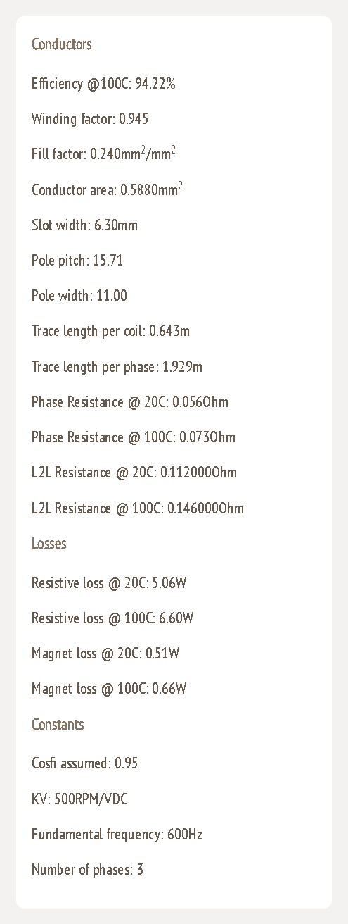
Conductors
| Parameter | Meaning |
|---|---|
| Efficiency @100C | Efficiency with a hot winding. Copper resistance rises about 0.39 %/K, so this is the realistic value for continuous operation. |
| Winding factor | How effectively the winding links the magnet flux (1.0 = ideal). |
| Fill factor (mm²/mm²) | Share of the winding area that is copper. |
| Conductor area (mm²) | Copper cross-section carrying the phase current. This is the value used for current density (guide 5). |
| Slot width (mm) | Width available for each coil side. |
| Pole pitch | Arc length of one pole at the rotor outer diameter: π × OD / poles. Example: π × 60 / 12 = 15.71 mm. |
| Pole width | Arc length covered by magnet: pole pitch × span. Example: 15.71 × 0.70 = 11.00 mm. |
| Trace length per coil / per phase (m) | Total copper track length. It drives the resistance. |
| Phase resistance @ 20C / 100C (Ω) | Resistance of one phase, cold and hot. |
| L2L resistance @ 20C / 100C (Ω) | Resistance between two terminals = 2 × phase resistance. Use it to check against a measurement on a real motor. |
Losses
| Parameter | Meaning |
|---|---|
| Resistive loss @ 20C / 100C (W) | Copper (I²R) loss at the phase current: 3 × Iph² × Rph. Example: 3 × 5.49² × 0.056 = 5.06 W. |
| Magnet loss @ 20C / 100C (W) | Estimated eddy-current loss in the magnets. |
Constants
| Parameter | Meaning |
|---|---|
| Cosfi assumed | Power factor used to calculate the phase current (0.95). |
| KV (RPM/VDC) | Nominal speed divided by DC voltage. Example: 6000 / 12 = 500 RPM/V. |
| Fundamental frequency (Hz) | Electrical frequency at nominal speed: RPM × poles / 120. Example: 6000 × 12 / 120 = 600 Hz. |
| Number of phases | 3 |
Indicative price
The indicative price appears once the configuration has at least one simulation and no red warnings.
- Quantity: enter an order quantity from 1 to 100. Unit Price and Total Price update to match.
- Price chart button (orange bars icon): shows the volume price table for 1, 5, 10, 20, 50 and 100 units.
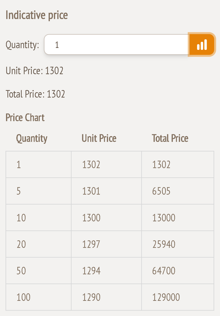
The price follows the motor's power rating. It is indicative only: contact Turncircles for a binding quotation.