1. Getting started with the Configurator
Page layout
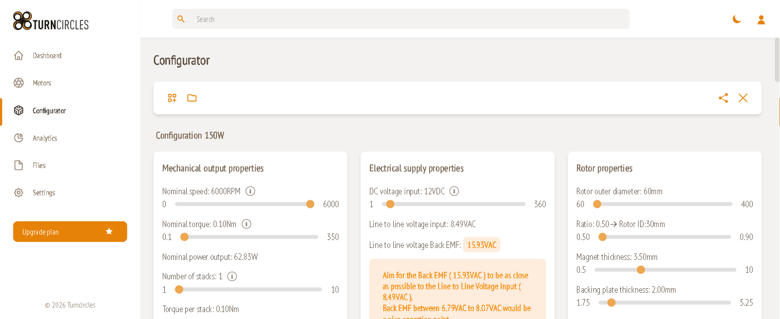
Open a configuration from Configurator in the left sidebar. The page has three parts, from top to bottom:
- Toolbar, with the configuration name below it.
- Design cards, where you set the motor up and see instant analytical results:
- Mechanical output properties
- Electrical supply properties
- Rotor properties
- Stator properties
- Analytical Calculation Results, including Other parameters and Indicative price
- Starting Simulations
- Simulation results, which show the finite-element results for each revision, the efficiency map and the Compare view.
Toolbar
| Icon | Name | Use it to |
|---|---|---|
| Grid with + | New | Start a new configuration |
| Folder | Open | Open one of your saved configurations |
| Share arrows | Share | Share the current configuration |
| × | Close | Close the current configuration |
Sliders and live recalculation
Most inputs are sliders. The current value appears next to the parameter name, and the numbers at each end are the allowed minimum and maximum. Some limits depend on other parameters. For example:
- The backing plate thickness range follows the magnet thickness.
- The maximum trace width follows the stator geometry.
- The minimum air gap follows the rotor diameter.
When you move a slider, every derived value on the page is recalculated straight away. Derived values are the plain text lines and the grey or coloured "pills".
Tooltips
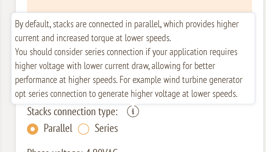
Click or hover the ⓘ icon next to a parameter to see what it does and how to choose it.
Colour-coded feedback
Many derived values are shown as coloured pills, and some get a warning box underneath. The colours mean:
| Colour | Meaning |
|---|---|
| Green | Within the recommended range |
| Amber / orange | Works, but outside the recommended range. Read the advice box. |
| Red | Outside a hard limit. The configuration is treated as invalid, and the indicative price is hidden until you fix it. |
| Grey | Information only |
The checks that drive these colours:
| Check | Amber when… | Red when… |
|---|---|---|
| Efficiency @20C | 70 % to below 85 % | below 70 % |
| Current density | above 8 A/mm² | above 12 A/mm² |
| Back-EMF vs. line-to-line supply voltage (ratio) | below 0.80 or above 0.95 | above 2.0 |
| Number of stacks (stator OD under 300 mm) | 4–6 stacks | more than 6 stacks |
| Air gap peak flux density | below 0.6 T | – |
| Magnet spacing | more than 10 % away from the ideal spacing | – |
| Air gap torque per stack | – | below the required torque per stack |
| Trace width | – | outside its allowed range |
| Stator (PCB) thickness | – | above 5 mm |
| Stator outer diameter | – | above 406 mm |
Recommended workflow
- Define the requirement. Set nominal speed, nominal torque and DC voltage (guides 2 and 3).
- Size the rotor. Choose the outer diameter, magnets, air gap and poles (guide 4).
- Design the winding. Set turns, layers, copper and traces until back-EMF and current density are green (guide 5).
- Check the analytical results. Confirm efficiency and air gap torque (guide 6).
- Simulate. Run a low-accuracy simulation, iterate, then confirm with medium or high accuracy (guide 7).
- Review. Read the results, generate an efficiency map and compare revisions (guides 8–10).
Tip: Get every pill green or amber before you submit a simulation. Simulations cost tokens and take hours. Analytical feedback is free and instant.