5. Stator properties
The stator is an ironless, multi-layer PCB winding. There's no iron core, so there are no cogging torque or core losses. The winding parameters on this card decide the motor's voltage constant (back-EMF), its resistance and its current-carrying capacity.
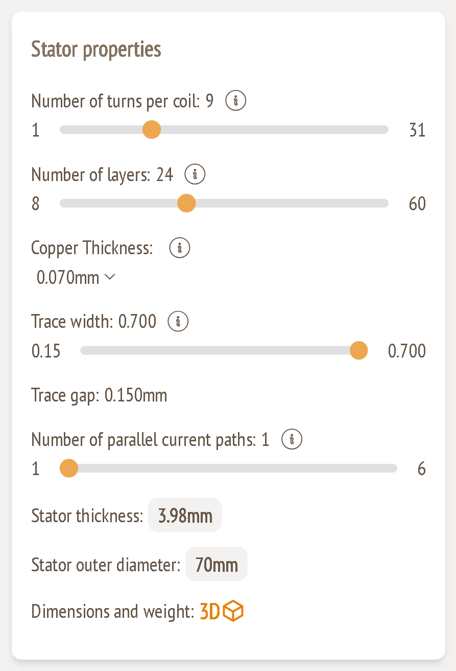
Inputs
Number of turns per coil
Range: 1 – 31
- More turns give a higher back-EMF and a lower current for the same torque. This suits higher supply voltages.
- Fewer turns give a lower back-EMF and a higher current, so you get more torque and speed from a low supply voltage.
This is the main knob for matching the back-EMF to your DC voltage (guide 3).
Number of layers
Range: 8 – 60
This is the number of copper layers in the PCB stator.
- More layers give more copper, lower resistance and better current distribution. They also increase back-EMF, stator thickness and cost.
- Fewer layers give a thinner, cheaper stator with less current capacity.
Watch the resulting stator thickness: it widens the magnetic gap between the rotors and so lowers the flux density (guide 4).
Copper thickness
Options: 0.009, 0.012, 0.018, 0.035, 0.050, 0.070, 0.105, 0.140, 0.210, 0.400 mm
This is the copper foil thickness of each layer. For reference, 0.035 mm ≈ 1 oz and 0.070 mm ≈ 2 oz copper.
- Thicker copper carries more current with lower resistive loss, which suits high-current designs.
- Thinner copper suits low-current or space-limited designs, at the cost of higher resistance.
Trace width (mm)
Range: set by the design. Example: 0.15 – 0.700 mm
This is the width of each winding trace. Wider traces carry more current with lower resistance and run cooler. However, wide traces pick up more eddy-current loss from the rotating magnet field, and that loss grows with speed. Narrow traces reduce eddy loss but can overheat at high current.
The maximum is calculated from the rest of the design, so it can change when you change other parameters. A value outside the allowed range turns red.
Number of parallel current paths
Range: 1 – 6
This is how many parallel branches each phase is split into.
- More parallel paths share the current between branches, which lowers resistance and losses in high-current designs.
- Fewer paths keep the winding simpler and cheaper.
Adding paths also lowers the back-EMF seen at the terminals. Keep an eye on the Electrical card when you change it.
Calculated values
| Value | Meaning | Example |
|---|---|---|
| Trace gap | Clearance between neighbouring traces, derived from the geometry | 0.150 mm |
| Stator thickness | Total PCB thickness. Above 5 mm turns red. | 3.98 mm |
| Stator outer diameter | Overall diameter of the PCB stator. It's larger than the rotor, because the winding extends beyond the magnet ring. Above 406 mm turns red. | 70 mm |
| Dimensions and weight (3D) | Opens the same 3D model and weight summary as the Rotor card | – |
The copper cross-section that carries the phase current comes from these settings:
Conductor area = copper thickness × (number of layers / 2) × trace width
Example: 0.070 × 12 × 0.700 = 0.588 mm². This area sets the current density shown in the Electrical card.
Balancing the winding: a worked example
The example design shows:
- Back-EMF 15.93 VAC against 8.49 VAC available (amber, too high)
- Current density 9.34 A/mm² (amber, too high)
To fix both:
- Reduce the turns per coil (for example 9 → 5). The back-EMF drops roughly in proportion to the turns.
- Fewer turns also means less torque per ampere. Check that the air gap torque in the Analytical results still exceeds the torque per stack (guide 6). The example has plenty of margin: 0.20 Nm against 0.10 Nm needed.
- The phase current comes from the required power and the supply voltage, so turns alone won't lower the current density. Bring it under 8 A/mm² with more copper: a thicker copper thickness (0.070 → 0.105 mm) or more layers.
- Check the stator thickness and air gap flux density again, because both move with the layer count.