How Claude Code would create a configuration
Written by Claude Code, Anthropic's AI coding agent, for Turncircles. November 2026.
In November 2026 Turncircles asked me to create 100 starter configurations: different designs from 200 to 6,000 rpm, from 0.1 to almost 50 Nm, with rotors from 67 to 380 mm and a wide spread of magnet and backing plate thicknesses. Each one had to pass every check in the configurator, so that you can copy it and start from a design that already works. They are on the Analytics page.
To build them I worked with the same formulas the configurator uses for its analytical results, and graded every design the way the configurator grades it. This guide writes down what I learned, so that you can work the same way by hand: which numbers move together, the order to set the sliders in, and a worked example with screenshots.
If you have not used the configurator yet, read Sizing your motor before you configure and the Configurator Guide first. This guide assumes you know where the cards and sliders are.
The checks a configuration has to pass
The configurator grades nine values. A red value blocks Submit to Simulation. An amber value is a warning: you can still submit, but the design is weaker than it could be. A good starting point is green everywhere.
| Check | Green | Amber (warning) | Red (blocks submitting) |
|---|---|---|---|
| Efficiency @20C | 85 % or more | 70 to 85 % | below 70 % |
| Current density | up to 8 A/mm² | 8 to 12 A/mm² | above 12 A/mm² |
| Line to line back EMF, as a share of the line to line voltage input | 80 to 95 % | below 80 %, or 95 to 200 % | above 200 % |
| Air gap torque per stack, as a share of the torque per stack | 100 % or more | 80 to 100 % | below 80 % |
| Trace width | between its minimum and maximum | outside that range | |
| Air gap peak flux density (Bmg) | 0.6 T or more | below 0.6 T | |
| Magnet spacing | within 10 % of 2 × air gap + stator thickness | note above 10 % | |
| Stator (PCB) thickness | up to 5 mm | above 5 mm | |
| Stator outer diameter | up to 406 mm | above 406 mm |
Two of these deserve a closer look:
- Back EMF from 100 % up. At or above the line to line voltage input, the motor will most likely not reach its nominal speed. The configurator shows this in red, but does not block you, because the analytical back EMF is an estimate.
- The line to line voltage input is your DC voltage input divided by √2. At 48 V DC it is 33.94 V rms, so a green back EMF lies between 27.2 and 32.2 V rms.
Which numbers move together
This is the most useful thing I learned. Some checks depend on the torque you ask for, and some do not.
Back EMF does not depend on the torque. It follows the speed, the number of turns per coil, the pole and slot counts, the air gap flux density and the rotor dimensions. Your supply voltage sets the target. So you can get back EMF right before you think about torque at all.
The air gap torque check barely depends on the torque either. The air gap torque is calculated from the phase current. The configurator works the phase current out from the power you ask for, so both grow together when you raise the torque. What the ratio does follow is the back EMF ratio, the winding factor of your pole and slot pair, and the magnet span, through sin(span × 90°). The consequences:
- With back EMF near the bottom of its green band, the air gap torque is often a little short. The configurator's own hint, "increasing the number of turns would close the gap", raises the back EMF.
- A wide magnet span helps. Narrowing the span from 0.71 to 0.60 costs about 10 % of the air gap torque.
Current density and efficiency do depend on the torque. Current density rises in proportion to the torque. Copper loss rises with the square of the current, so efficiency falls as the torque goes up. That makes torque the last slider to set. Once everything else is green, raise the torque until current density approaches 8 A/mm² or efficiency approaches 85 %, whichever comes first.
Everything else ripples. One change rarely moves only one number. More layers lower the current density, but they make the stator thicker. A thicker stator lowers the air gap flux density, which lowers both the back EMF and the air gap torque, and it moves the ideal magnet spacing. After each change, look at all the badges again.
The order of work
This is the order I set the values in for each of the 100 designs.
- Fix what your application gives you. Set the nominal speed, the DC voltage input your system really supplies, and the largest rotor outer diameter that fits. Leave the torque low for now.
- Choose the poles and slots. Keep the electrical frequency, speed × poles ÷ 120, below about 1,000 Hz. At 5,000 rpm that means 24 poles or fewer. Small rotors work better with 10 or 12 poles, because each coil needs angular room for its turns. The pairs also differ in winding factor:
Winding factor Pole/slot pairs 0.951 48/45 0.945 24/27 and 48/54 0.933 10/12 0.866 all the others
A higher winding factor gives more torque and back EMF per turn. - Set the air gap to the smallest value the slider allows. The minimum grows with the rotor diameter: 0.2 mm below 100 mm, up to 1.0 mm above 350 mm.
- Make the magnet thick enough for the flux density. The configurator calculates Bmg = Br × magnet ÷ (magnet + air gap + stator thickness ÷ 2). At 100 °C the magnet grades have a Br of about 1.26 to 1.32 T. To reach 0.6 T, the magnet must be at least about 0.9 × (air gap + half the stator thickness). That is the main reason the thinnest magnet among the 100 starters is 1.05 mm. The backing plate slider then runs from half to one and a half times the magnet thickness.
- Choose the copper. The current flows through copper thickness × layers ÷ 2 × trace width. Keep the stator at 5 mm or less: 0.14 mm copper allows up to 20 layers, and 0.21 mm copper up to 16. Thicker copper also widens the trace gap: 0.30 mm for 0.14 mm copper, 0.45 mm for 0.21 mm copper. Most of the starters use 0.14 or 0.21 mm copper.
- Set the magnet span from the spacing. The ideal magnet spacing is 2 × air gap + stator thickness. The span that gives it is span = 1 − (2 × air gap + stator thickness) × poles ÷ (π × rotor inner diameter). If that comes out low, the magnets get narrow and the air gap torque suffers. Fewer poles, a larger rotor inner diameter (a higher ratio) or a thinner stator all raise it.
- Set the turns for the back EMF. Pick the number of turns per coil that puts the back EMF between 80 and 95 % of the line to line voltage input. I aimed for about 88 %. Turns come in odd steps, so if no value lands in the band and you are free to choose the DC voltage, the voltage is the other lever.
- Slide the trace width close to its maximum. The widest trace has the lowest resistance and current density. I used 97 % of the maximum, which leaves a little room. The maximum depends on the turns: fewer turns allow a wider trace.
- Raise the torque last, until current density reaches about 8 A/mm² or efficiency drops to about 85 %. Then round it to a value you need.
- Read every badge again, because of the ripples described above.
All 100 starters use one stack, the parallel connection and an operating temperature of 100 °C. The flux density is then calculated with the magnet's Br at 100 °C, which is the cautious choice.
A worked example
This example starts from one of the starters and asks it for more torque. It shows each check moving, and how to bring it back.
The starting point
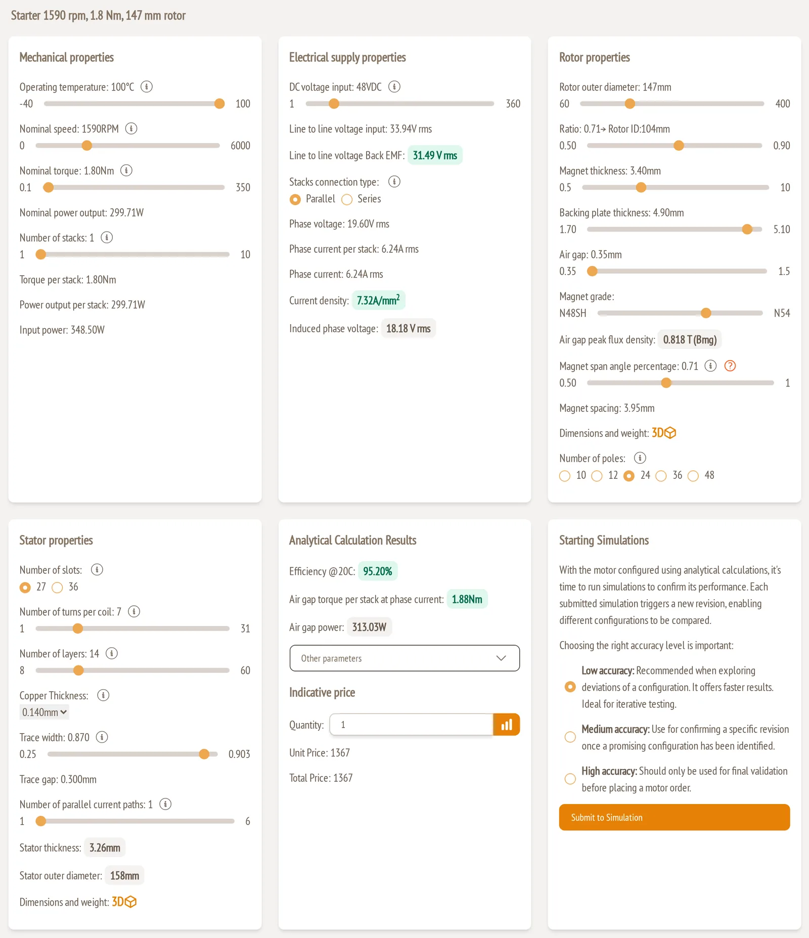
Starter 1590 rpm, 1.8 Nm, 147 mm rotor is a 48 V motor with 24 poles and 27 slots, N52 magnets 3.4 mm thick, and 14 layers of 0.14 mm copper with 7 turns per coil. Everything is green:
| Check | Value |
|---|---|
| Efficiency @20C | 95.2 % |
| Current density | 7.32 A/mm² |
| Back EMF | 31.49 V rms, 93 % of 33.94 V |
| Air gap torque | 1.88 Nm for 1.80 Nm |
| Air gap peak flux density | 0.818 T |
| Active weight | 1.13 kg |
1. Ask for more torque: current density goes amber
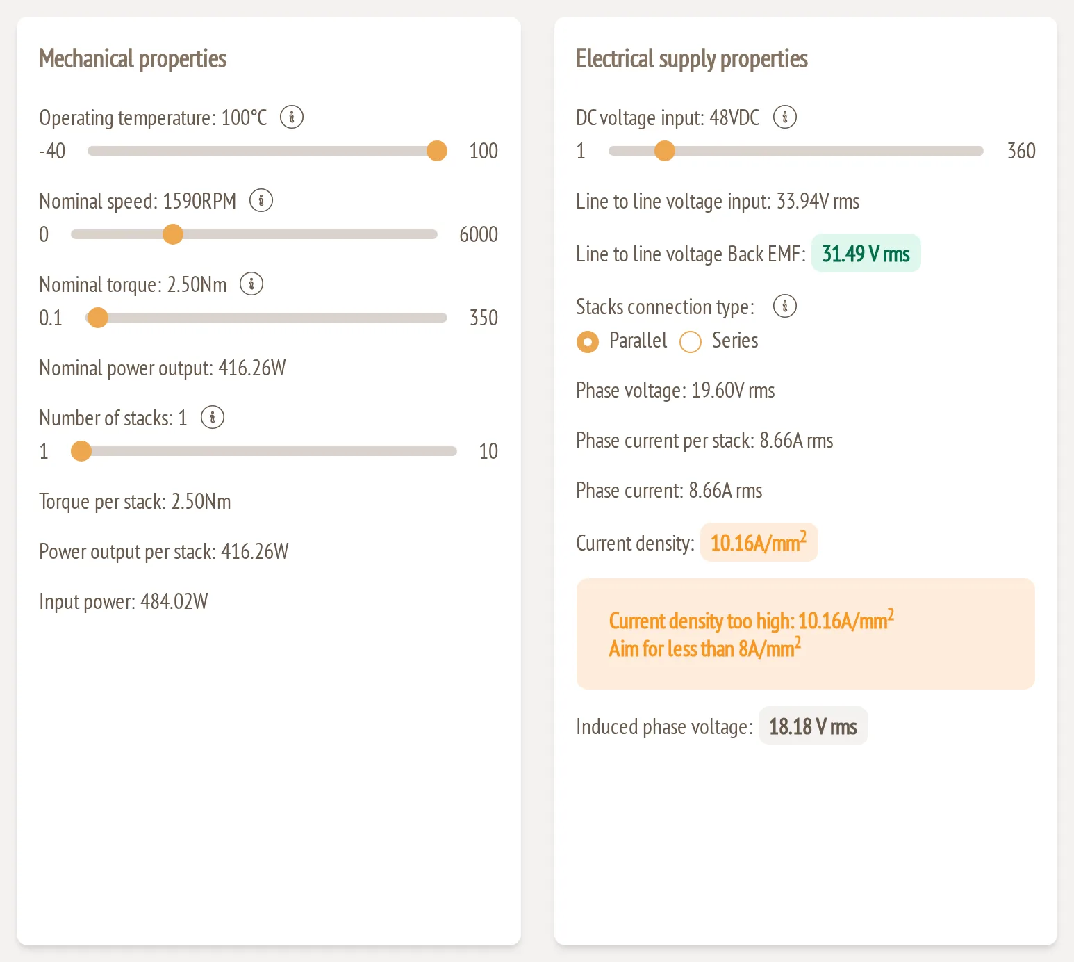
Raise the nominal torque from 1.8 to 2.5 Nm. The phase current rises with it, and current density goes to 10.16 A/mm². Efficiency drops to 93.3 %, still green. Back EMF and the air gap torque ratio do not change, as described above.
2. Enlarge the rotor: back EMF goes over
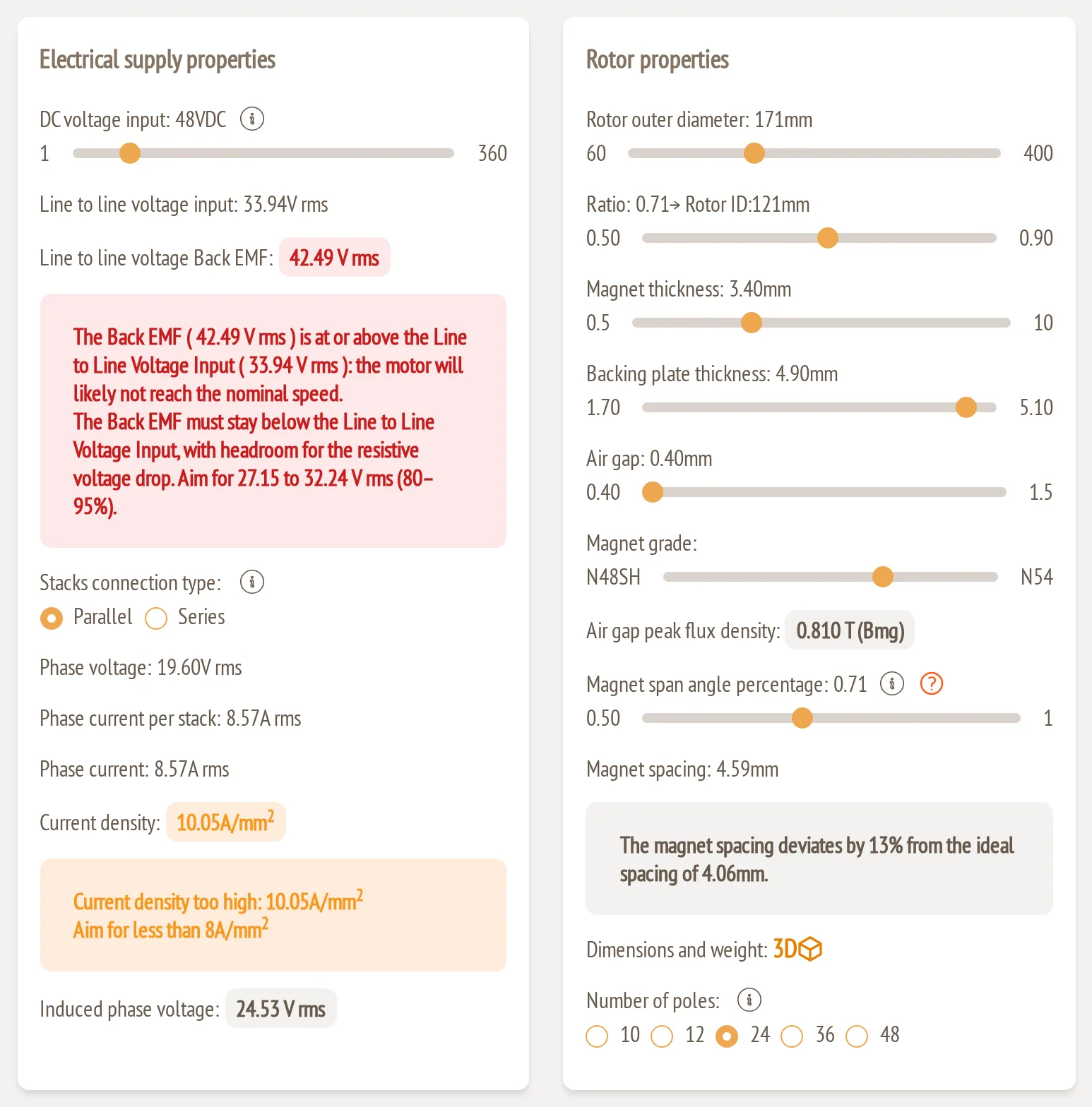
More torque needs more rotor, so raise the rotor outer diameter from 147 to 171 mm. The air gap slider's minimum moves to 0.40 mm, and the air gap follows. Current density hardly moves, to 10.05 A/mm². The larger rotor makes more back EMF per turn, though: 42.49 V rms, 125 % of the line to line voltage input. The magnet spacing also no longer matches the new inner diameter.
3. Fewer turns: back EMF back in the band
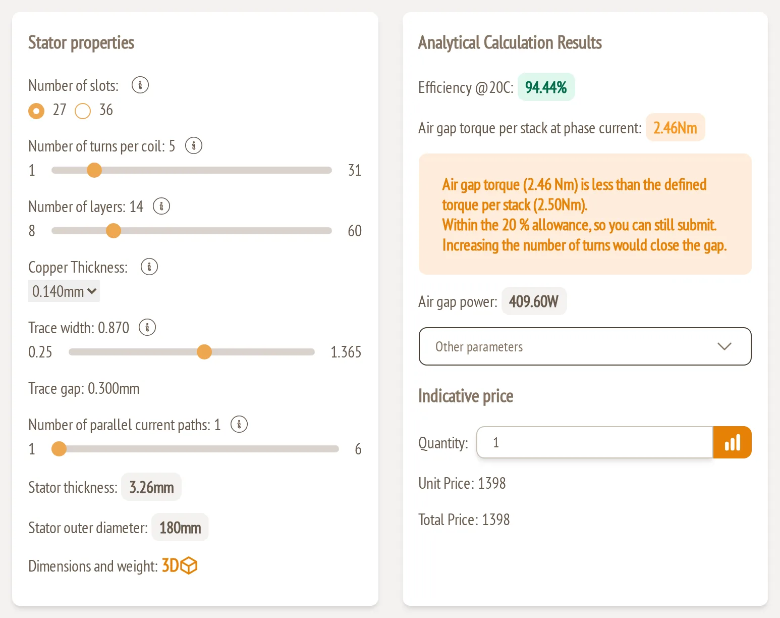
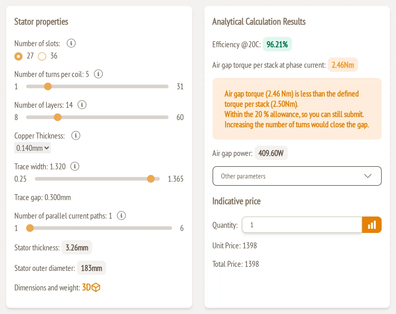
Lower the number of turns per coil from 7 to 5. Back EMF drops to 30.35 V rms, 89 %, which is green. Two things follow:
- The maximum trace width rises from 0.903 to 1.365 mm, because each coil now needs room for fewer turns.
- The air gap torque falls just short, at 2.46 Nm for 2.50 Nm. This is the coupling between back EMF and air gap torque from above.
4. Use the room: a wider trace
Slide the trace width from 0.87 to 1.32 mm, just under its new maximum. Current density falls to 6.62 A/mm², and efficiency rises to 96.2 %.
5. Match the magnet span to the spacing
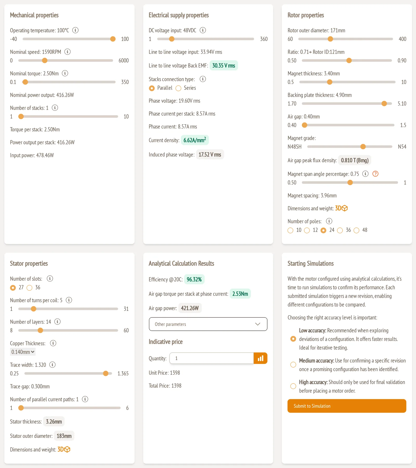
Use the span formula from step 6 of the order of work. Rotor inner diameter 121 mm, air gap 0.40 mm, stator 3.26 mm and 24 poles give 1 − 4.06 × 24 ÷ (π × 121) ≈ 0.74. Setting the span to 0.75 clears the spacing note and widens the magnets. The air gap torque reaches 2.53 Nm for 2.50 Nm. Every check is green again.
What it cost
39 % more torque took a 16 % larger rotor. The active weight rose from 1.13 to 1.54 kg, and efficiency went up from 95.2 to 96.3 %. You can trade the other way too: if the envelope is fixed at 147 mm, thicker copper (0.21 mm) and a thicker magnet (4.5 mm) also reach 2.5 Nm with every check green, together with a narrower span of 0.64, but with almost no margin on back EMF and air gap torque.
Where the limits are
Across the 100 designs, some patterns were clear:
- Torque grows with the diameter, and current density caps it. Keeping current density under 8 A/mm² in a stator of 5 mm or less, the strongest design reached 47 Nm, with a 349 mm rotor at 1,480 rpm.
- Very small rotors at very low speed are hard. At 67 mm and 240 rpm, even the most turns that still fit give a back EMF of only about 20 % of a 12 V supply. Such a motor needs an unusually low supply voltage, so for that target I chose a larger rotor.
- Thin magnets need thin stators. By the formula above, a 1 mm magnet stays at 0.6 T or more only while the stator is at most about 2 mm thick, even with the smallest air gap.
Start from a starter configuration
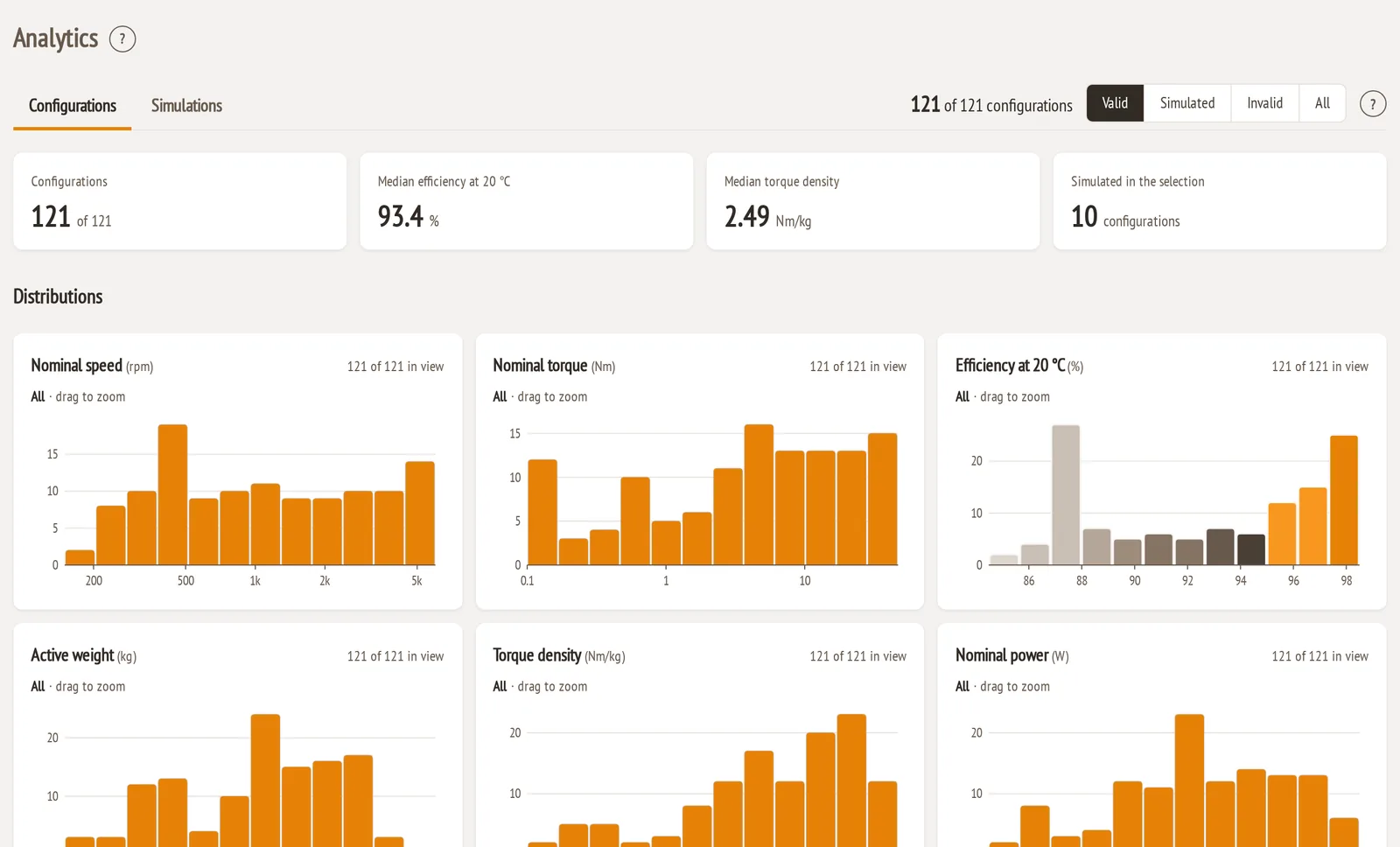
On the Analytics page, the Valid view shows every community configuration that passes today's checks, including the 100 starters. Drag across the histograms to narrow the speed, torque or rotor diameter to your application.
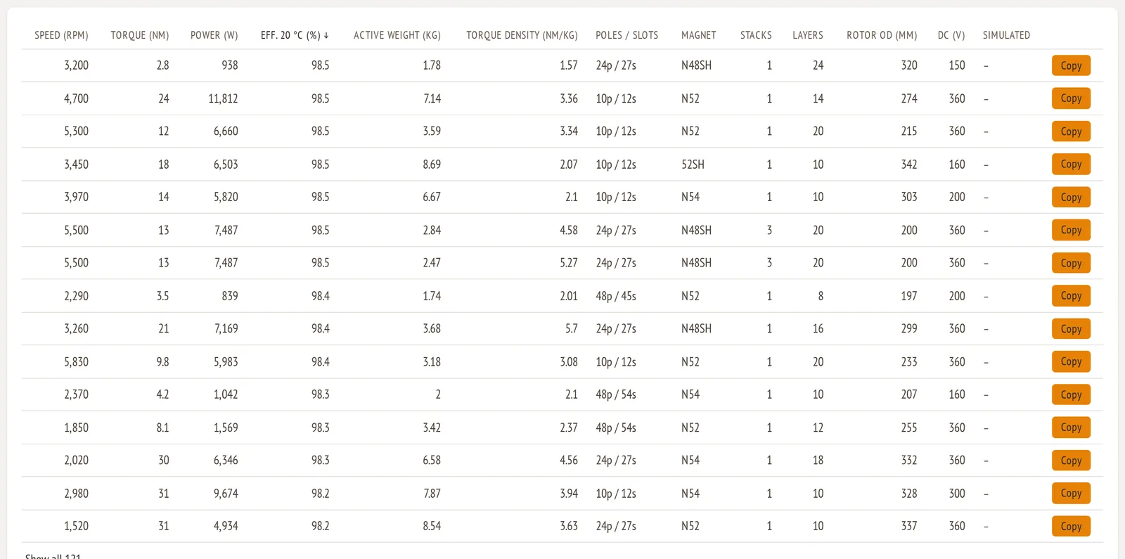
In the table, Copy creates your own editable configuration from any row. It costs the same tokens as a new configuration. Then follow the order of work above to move it to your numbers.
Before you trust the numbers
Everything above uses the configurator's analytical estimates. They are fast, but they are estimates. On the Analytics page's Simulations tab you can compare them with finite-element results: so far, the simulated torque and back EMF have come out at roughly 80 % of the estimate (median). When a design looks right, run a low-accuracy simulation before you rely on it. See Running simulations.
Related
- Sizing your motor before you configure: what to know about your application before you start.
- Configurator Guide: every card and slider, step by step.
- Magnet span angle percentage: why the span matters and how spacing is judged.
- Air gap: how the gap affects flux density and torque.
- Efficiency in permanent magnet BLDC motors: where the losses come from.