Magnet span angle sweep
The magnet span angle percentage is the fraction of each pole pitch that is covered by magnet. It moves torque, magnet mass and the shape of the back-EMF at the same time, and the best value depends on your goal and on the motor. The ideal theory gets you close, but the true optimum has to be found by simulation (see Magnet span angle percentage for the physics).
A span sweep does this in one submission. You list several spans, every span becomes its own revision, and you compare the revisions side by side.
The examples on this page come from a real 48-pole, 54-slot design: 300 mm rotor, 252 mm rotor ID, 2 mm magnets, 0.80 mm air gap and a 2.38 mm stator, rated 8 Nm at 440 RPM. It was swept at five spans between 0.70 and 0.82.
Before you sweep
Settle the other parameters first
A sweep runs the same changes, once per span. Whatever else you changed since the revision you compare with goes into every span of the sweep. Get the diameters, magnet thickness, air gap, poles, slots and winding right first, then sweep the span on its own. Otherwise you can't tell what caused a difference.
Pick a starting span
Click the orange ? next to Magnet span angle percentage in the Rotor properties card. It shows the typical targets: 0.82 for an FOC drive and 0.70 near the torque-ripple optimum.
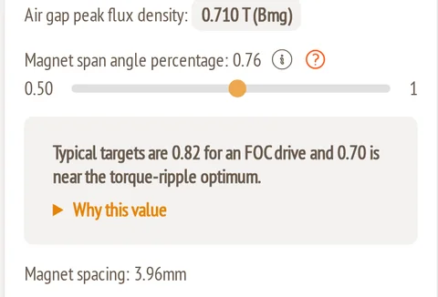
A third starting point is the spacing rule from the definition page, which puts the spacing between magnets equal to the magnetic gap:
αrule = 1 − (2 × air gap + stator thickness) × number of poles ÷ (π × rotor ID)
For the example: 1 − (2 × 0.80 + 2.38) × 48 ÷ (π × 252) = 0.76.
Choose the spans
Three to five spans are enough for a first pass. A good pattern is the rule value, the two typical targets and one point between them, for example 0.70, 0.76, 0.82. Then add a second, finer sweep (steps of 0.02) around the best point.
Setting up the sweep
- Set the span you want as the reference on the Rotor properties card. It becomes the first row of the sweep.
- Click Submit to Simulation.
- Choose the Accuracy. A sweep is exploration, so Low is the right level.
- Check Compared with and the table of changed parameters below it. These changes go into every span.
- Click + Sweep magnet span angles, then + Add span for every extra span, and type its value.
- Check the totals at the bottom and click Submit N revisions.
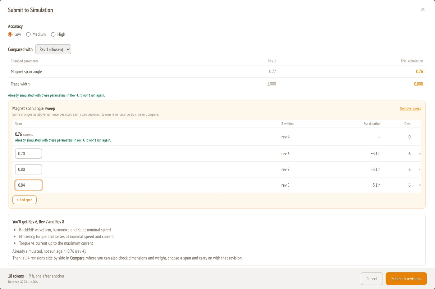
| Column | Meaning |
|---|---|
| Span | The span for that revision. The first row is the current span from the Rotor properties card. Values from 0.50 to 1.00, with at most 2 decimals. |
| Revision | The revision number the span will get. |
| Est. duration | Estimated solver time for that revision. |
| Cost | Tokens for that revision. |
Good to know:
- Spans that were already simulated are not run again. If a span with exactly the same parameters exists as a revision, the row says "Already simulated with these parameters in rev N. It won't run again." and costs 0 tokens. In the screenshot, 0.76 is already Rev 4.
- Revisions run one after another, not in parallel. The footer shows the total tokens, the total time and your balance before and after.
- Up to 10 spans per submission.
- To cancel the sweep before submitting, click Remove sweep.
What each revision runs
Every revision in the sweep gets the same set of simulations:
- BackEMF at nominal speed: waveform, harmonics and Ke.
- Efficiency at nominal speed and nominal current: efficiency, torque and losses.
- Max Current: torque against current up to the maximum current.
Following the revisions
The revision bar shows the span of the revision you are looking at, so the revisions of a sweep are easy to tell apart. Step through them with ‹ ›. Chosen: Rev N → jumps to the revision that is currently chosen.

Reading one revision
Harmonics tab
Open the BackEMF card's Harmonics tab. It is the most useful view for a span sweep, because the span is one of the strongest levers on the harmonics. See guide 8 for every element of the tab.
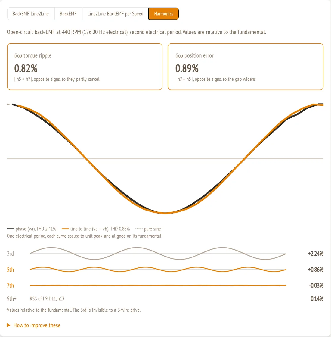
At span 0.70 in the example:
- 5th harmonic +0.86% and 7th −0.03%. These reach the drive and set the two cards at the top: 6ω torque ripple 0.82% and 6ω position error 0.89%.
- 3rd harmonic +2.24%. It is shown in brown because a star-connected 3-wire drive never sees it (see When the 3rd harmonic gets strong below).
- The phase and line-to-line curves lie almost exactly on the sine. All harmonics here are below 1% except the 3rd.
Efficiency tab
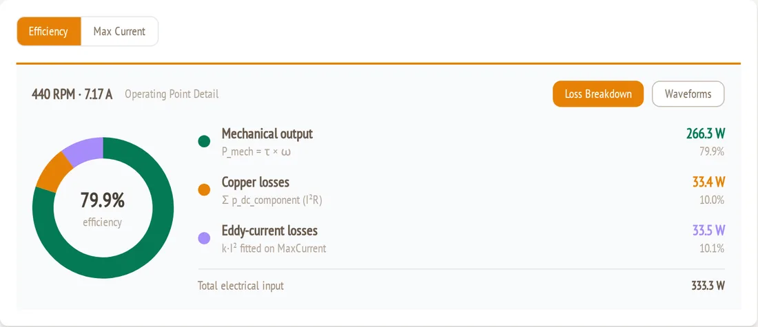
The Efficiency tab of the Max Current card shows the nominal operating point: mechanical output, copper loss, eddy-current loss and efficiency. Waveforms shows the phase voltage and current and the torque.
Comparing the spans
Click Compare in the revision bar. Each revision is a column, with its span under the revision number.
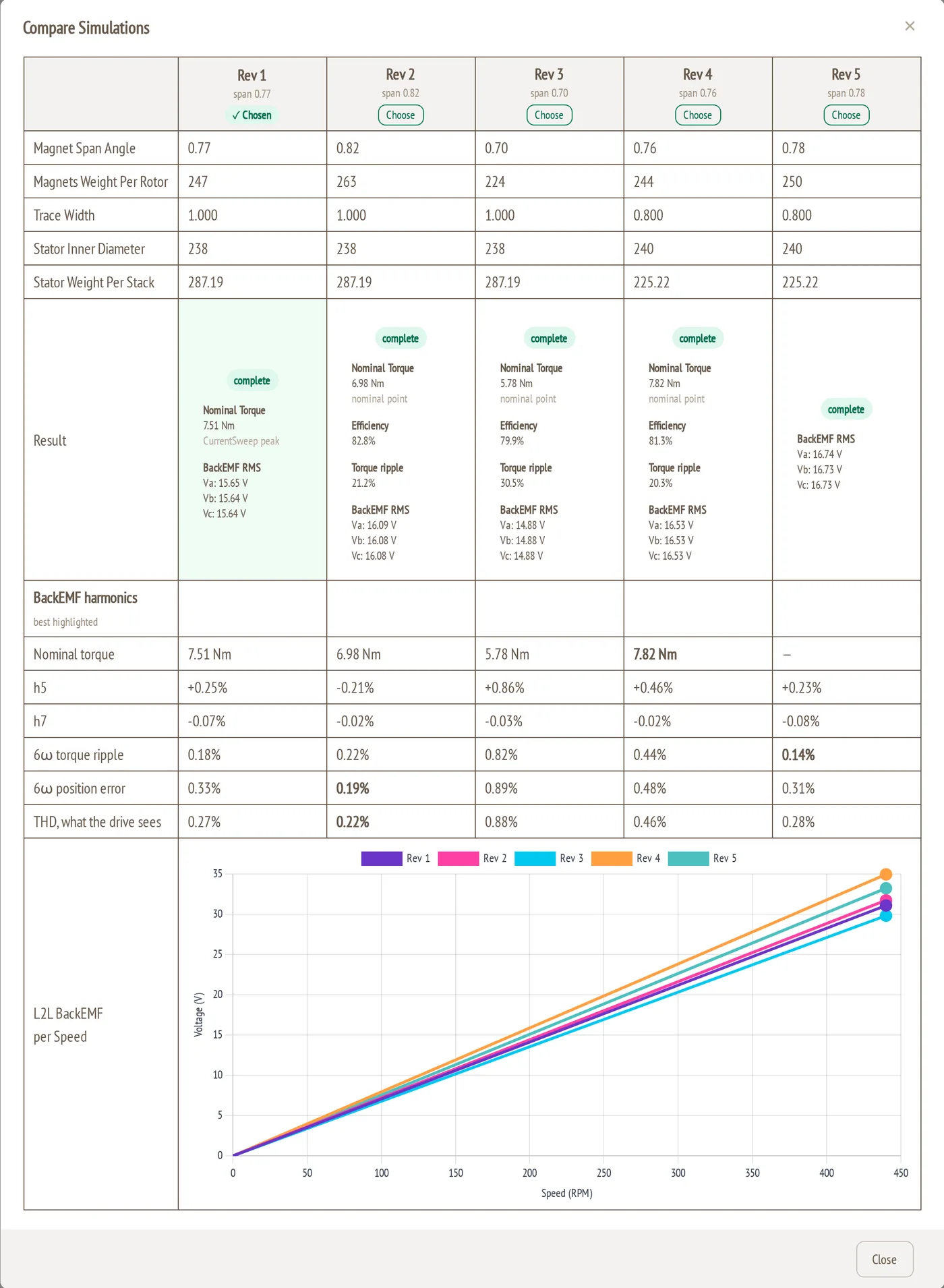
The example sweep in numbers. Revisions 1 to 3 belong together, and so do revisions 4 and 5 (narrower traces, see above):
| Revision | Span | Magnets per rotor | Back-EMF (V rms, phase) | h5 | h7 | 6ω torque ripple | 6ω position error | THD (line-to-line) | h3 (phase) |
|---|---|---|---|---|---|---|---|---|---|
| Rev 3 | 0.70 | 224 g | 14.88 | +0.86% | −0.03% | 0.82% | 0.89% | 0.88% | 2.2% |
| Rev 1 | 0.77 | 247 g | 15.64 | +0.25% | −0.07% | 0.18% | 0.33% | 0.27% | 6.3% |
| Rev 2 | 0.82 | 263 g | 16.08 | −0.21% | −0.02% | 0.22% | 0.19% | 0.22% | 8.6% |
| Rev 4 | 0.76 | 244 g | 16.53 | +0.46% | −0.02% | 0.44% | 0.48% | 0.46% | 4.0% |
| Rev 5 | 0.78 | 250 g | 16.73 | +0.23% | −0.08% | 0.14% | 0.31% | 0.28% | 4.6% |
Torque: read it from the back-EMF
In a coreless motor, torque at a given current is proportional to the back-EMF (Kt = Ke). The back-EMF comes from an open-circuit simulation and is very clean, so it is the most reliable way to compare the torque of two spans. Use the BackEMF RMS values in the Result row, or the slopes in L2L BackEMF per Speed.
From 0.70 to 0.77 to 0.82 (revisions 3, 1, 2), the magnet mass grows by 10% and then by another 6.5%. The back-EMF grows by 5.1% and then by 2.8%. This is the diminishing return that the ideal sin(α × 90°) model predicts, and the simulated values sit almost exactly on it. In this design, leakage between the magnets doesn't yet eat the gain at 0.82, even though the spacing there (2.97 mm) is 25% below the spacing rule. Torque per gram of magnet still falls: relative to 0.70, it is 0.95 at 0.77 and 0.92 at 0.82.
Harmonics
- h5 changes sign between 0.77 and 0.82: +0.86% at 0.70, +0.25% at 0.77, −0.21% at 0.82. The ideal model puts this zero at 0.80, and the example agrees.
- h7 stays below 0.1% at every span. The 54-slot winding filters it out.
- The best position error and THD are at 0.82, where h5 and h7 are smallest together. The lowest 6ω torque ripple is at 0.78 and 0.77, where h5 and h7 nearly cancel.
- 0.70 is not the ripple optimum for this motor. It has the largest h5 and therefore the largest 6ω ripple of the sweep. The typical target of 0.70 comes from other motors. This is exactly why a sweep is worth running.
Every span in this sweep keeps the drive-visible harmonics below 1%, so all of them would run smoothly. The decision is between magnet mass and back-EMF.
Picking a span for your goal
| Your goal | What to look at | Choice in the example |
|---|---|---|
| Sensorless FOC accuracy | 6ω position error, THD | 0.82 (Rev 2) |
| Smooth torque | 6ω torque ripple | 0.77 – 0.78 (Rev 1, Rev 5) |
| Most torque from the rotor | Back-EMF RMS | 0.82 (Rev 2) |
| Least magnet for the torque you need | Back-EMF ÷ magnet weight, with a minimum back-EMF | 0.70 – 0.77 |
| More voltage headroom at top speed | L2L BackEMF per Speed | A narrower span, then fine-tune turns |
For the full list of goals and their typical ranges, see Choosing a span for your goal.
Choosing the revision
When you have decided, click Choose this revision in the revision bar, or Choose in a column header of Compare. The dialog lists every parameter that will be overwritten, for example Magnet span angle: 0.76 → 0.70. Click OK to copy that revision's parameters into the configuration.
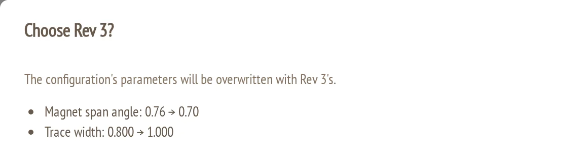
- Choosing doesn't run anything and costs no tokens.
- The chosen revision gets a green ✓ Chosen badge in the revision bar and in Compare.
- Your next submission is compared with the chosen revision by default.
When the 3rd harmonic gets strong
Sometimes a sweep shows a phase back-EMF that is clearly not sinusoidal, while the line-to-line back-EMF looks perfect. This is the 3rd harmonic. The example below is a 24-pole, 36-slot motor at span 0.82, simulated at 2000 RPM:
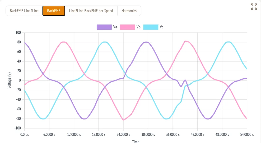
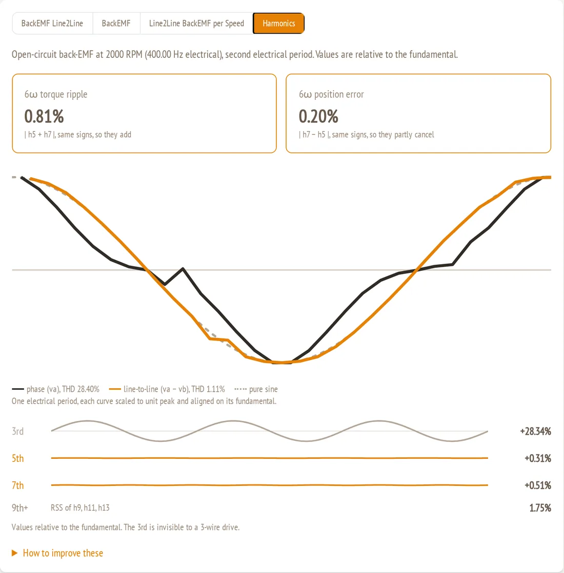
The phases have pointed peaks and flat shoulders around every zero crossing. The Harmonics tab gives the reason: a 3rd harmonic of +28.3%, while h5 and h7 stay at 0.3% and 0.5%:
Why the drive doesn't see it
The 3rd harmonic is the same in all three phases, at the same moment. In the line-to-line voltage (phase A minus phase B), it cancels. In the example, the phase THD is 28.4% but the line-to-line THD is only 1.1%. A star-connected motor with three wires can't drive a current at the 3rd harmonic either, so it adds no torque ripple and no loss.
The small kink in the Va and Vc traces is a single time step of numerical noise from the rotating mesh. It is not part of the motor's waveform.
What makes it strong
The phase h3 is the product of two things:
- How much 3rd harmonic the magnets put into the air gap. For an ideal magnet this is proportional to sin(3 × α × 90°) ÷ 3. It is zero at α = 2/3 (0.67) and grows as the span gets wider. A larger magnetic gap compared with the pole pitch damps it.
- How strongly one coil picks it up. This depends on the coil pitch in electrical degrees, 180° × number of poles ÷ number of slots. Each PCB coil is a spiral whose turns go from almost zero width up to the full coil pitch, so the coil collects the harmonic over that whole range of widths.
The second factor is decisive. Here is how the eight pole/slot combinations compare. The pickup is an estimate of how strongly the winding collects the 3rd harmonic relative to the fundamental, from the coil pitch and the way each phase's coils are distributed:
| Poles / slots | Coil pitch (electrical) | 3rd-harmonic pickup | Phase h3 |
|---|---|---|---|
| 12/18, 24/36, 36/54 | 120° | 1.3 | Strong: about 28% at span 0.82 in the example |
| 24/27, 48/54 | 160° | 0.4 | Moderate: 2% to 9% across the example sweep |
| 48/45 | 192° | 0.14 | Weak |
| 12/9, 36/27 | 240° | ≈ 0 | Practically none |
A 120° coil picks up the 3rd harmonic more strongly than the fundamental. At the same span of 0.82, the 24/36 motor has 28.3% phase h3, and the 48/54 motor from the sweep above has 8.6%. In both, the line-to-line h3 is below 0.4%.
Within one motor, the span moves h3 as predicted. In the 48/54 sweep it rises from 2.2% at 0.70 to 6.3% at 0.77 and 8.6% at 0.82.
When to act on it
- Star connection with three wires (the normal case): ignore h3. Judge the span by h5, h7 and the line-to-line waveform, as above.
- Delta connection: h3 drives a current that circulates inside the delta, even with no load connected, and heats the winding. Keep h3 low with a span near 0.67, or use a combination with a longer coil pitch.
- Measuring the phase voltage against the motor's neutral, for example in a test: expect the peak phase voltage to be up to about h3 higher than the fundamental alone. The line-to-line peak, which the DC bus has to cover, is not affected.
Tips
- Sweep at Low accuracy, then confirm the chosen revision at Medium.
- Change only the span within a sweep. Check the changed-parameter table before you submit, and the parameter rows in Compare before you read the results.
- Use the back-EMF to compare torque, and the 6ω rows to compare smoothness and controllability.
- Don't judge a span by how sinusoidal the phase waveform looks. A strong h3 can make it look bad while the drive sees a clean waveform.
- Start a finer sweep (steps of 0.02) around the best point before you choose.
Related
- Magnet span angle percentage: the physics, the spacing rule and the goal table.
- 4. Rotor properties: where the span is set.
- 8. Reading simulation results: every element of the BackEMF and Harmonics tabs.
- 10. Comparing revisions: the Compare dialog in detail.