3. Electrical supply properties
This card links the motor to your power electronics. It turns the DC bus voltage into the AC voltage the inverter can deliver and compares that with the voltage the motor generates (its back-EMF). It also shows the resulting phase current and current density.
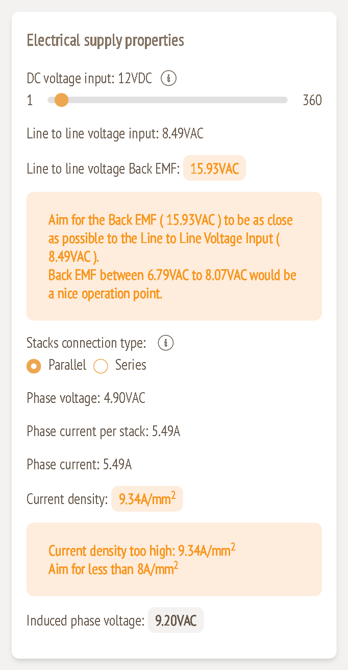
Inputs
DC voltage input (VDC)
Range: 1 – 360 VDC
This is the DC bus voltage of your battery or power supply, as seen by the motor controller. Higher voltage means lower current for the same power, which reduces wiring and copper losses. Make sure your supply can deliver the resulting current at the voltage you choose.
Stacks connection type
Options: Parallel (default) / Series
This applies only to multi-stack motors.
- Parallel: each stack sees the full supply voltage and the currents add up. This gives higher current and more torque at lower speeds. It is the right choice for most drive applications.
- Series: the stack voltages add up and the same current flows through every stack. This gives higher voltage and lower current draw, which is better for higher speeds, or for generators that must produce a high voltage at low speed, such as wind turbines.
Calculated values
Line to line voltage input (VAC)
This is the maximum line-to-line RMS voltage the inverter can make from the DC bus:
VLL = VDC / √2
Example: 12 V / √2 = 8.49 VAC.
Line to line voltage Back EMF (VAC)
This is the line-to-line RMS voltage the motor generates at nominal speed, calculated from the rotor and stator design. It is the most important number on this card. The inverter can only push current into the motor while its output voltage is higher than the back-EMF.
The card compares it with the line-to-line input voltage and suggests a target:
Back EMF between 0.80 × VLL and 0.95 × VLL would be a nice operation point.
In the example that is 6.79 – 8.07 VAC.
| Back-EMF / VLL | Colour | What it means |
|---|---|---|
| 0.80 – 0.95 | Green | Good use of the supply voltage, with headroom for control |
| below 0.80 or above 0.95 | Amber | Too low: current is higher than needed. Too high: the drive runs out of voltage near nominal speed. |
| above 2.0 | Red | The drive can't reach nominal speed. The configuration is invalid. |
In the example the back-EMF is 15.93 VAC against 8.49 VAC available (ratio 1.88), so it's shown in amber. The winding makes too much voltage for a 12 V bus.
How to bring the back-EMF into range:
- Lower it: use fewer turns per coil or fewer layers, a smaller rotor diameter, thinner magnets or a larger air gap.
- Raise the DC voltage if your system allows it.
- Raise it (if it's too low): do the opposite.
Phase voltage (VAC)
The phase (line-to-neutral) RMS voltage available from the supply: Vph = VLL / √3. Example: 8.49 / √3 = 4.90 VAC.
Phase current per stack / Phase current (A)
This is the RMS phase current needed to deliver the input power, assuming a power factor (cos φ) of 0.95:
Iph = Pin / (3 × Vph × 0.95)
Example: 76.62 W / (3 × 4.90 V × 0.95) = 5.49 A. With one stack, the per-stack and total values are the same. With several stacks, they depend on the connection type.
Current density (A/mm²)
This is the phase current divided by the copper cross-section that carries it:
J = Iph / (copper thickness × number of layers / 2 × trace width)
Example: 5.49 A / (0.070 mm × 12 × 0.700 mm) = 5.49 / 0.588 mm² = 9.34 A/mm².
Current density decides how hot the winding gets:
| Current density | Colour |
|---|---|
| up to 8 A/mm² | Green |
| 8 – 12 A/mm² | Amber: "Current density too high… Aim for less than 8 A/mm²" |
| above 12 A/mm² | Red |
To reduce current density: use thicker copper, wider traces, more layers or more parallel current paths (guide 5), or raise the DC voltage so less current is needed.
Induced phase voltage (VAC)
This is the back-EMF per phase: the line-to-line back-EMF divided by √3. Example: 15.93 / √3 = 9.20 VAC.
Tips
- Treat back-EMF matching and current density as your two main targets. Most stator changes move both, so adjust them together.
- For a first design, bring the back-EMF into the 0.80–0.95 band first, then fix the current density with copper and trace settings.