Magnet Span Angle Percentage
The magnet span angle percentage (written α, also called the pole arc ratio or pole arc to pole pitch ratio) is the fraction of each pole pitch that is covered by magnet. A rotor with 12 poles has a pole pitch of 360° / 12 = 30°. With α = 0.75, each magnet covers 22.5° and the remaining 7.5° between neighbouring magnets is empty.
- α = 1.00: the magnets touch and there is no spacing between them.
- α = 0.50: half of the rotor face is magnet and half is empty.
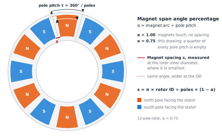
In an axial-flux motor the magnets are sectors of a ring, so the span is an angle and the gap between magnets grows with radius. The gap is smallest at the rotor inner diameter, which makes that the critical place to measure the magnet spacing:
s = π × rotor ID ÷ number of poles × (1 − α)
How the Span Shapes the Air-Gap Field
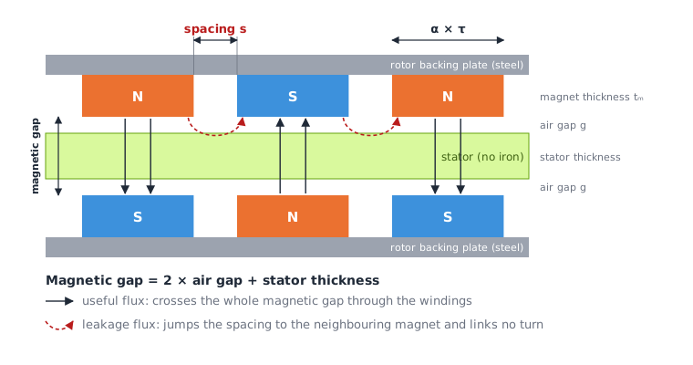
In a coreless axial-flux motor the stator sits between two rotor discs. Each magnet faces a magnet of the opposite polarity on the other disc, so the useful flux runs straight across the stator. The distance it has to cross is the magnetic gap: the air gap on both sides plus the stator thickness.
Seen by a coil moving past the rotor, the flux density is roughly a block: high over a north magnet, near zero over a spacing, negative over a south magnet. The span sets how wide each block is. Only the sinusoidal fundamental of that block produces useful torque with a sinusoidal drive current. Everything else is a harmonic.
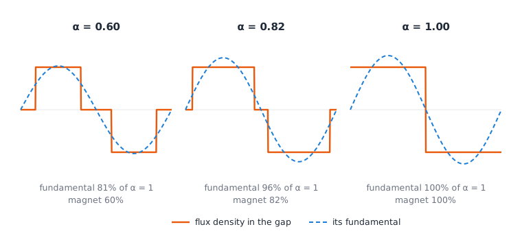
For an ideal block-shaped field, the fundamental and the harmonics follow simple expressions:
- fundamental ∝ sin(α × 90°)
- harmonic n ∝ sin(n × α × 90°) ÷ n (odd n only: 3rd, 5th, 7th, ...)
These two expressions explain most of what follows.
Influence on Back-EMF and Torque
Back-EMF and torque are the same quantity seen from two sides
When the rotor turns, the magnet flux sweeping past a coil induces a voltage in it. This is the back-EMF. When a current flows through the same coil, the same flux pushes on that current and produces torque. Both effects come from the amount of magnet flux that links the coil, so they always rise and fall together.
In SI units this link is exact: the back-EMF constant Ke (volts per rad/s of speed) and the torque constant Kt (newton-metres per ampere) are the same number. Everything below about torque therefore applies equally to back-EMF.
Why torque grows with sin(α × 90°)
With a sinusoidal drive current, only the fundamental of the air-gap field produces steady torque. Think of the fundamental as a weighting curve laid over each pole: it is highest at the pole centre and falls to zero at the pole edges.
- Magnet material at the centre of the pole sits where the weighting is high, so it contributes a lot of torque.
- Magnet material near the edges sits where the weighting is low, so it contributes little.
A magnet always grows from the centre outwards, so widening the span only ever adds material at the edges. The first part of the span does most of the work, and each further increase adds less than the one before. Adding up the weighting across a magnet of span α gives exactly sin(α × 90°).
Magnet mass behaves differently. Every slice of magnet weighs the same wherever it sits, so the mass grows in direct proportion to α.
Torque and magnet mass against span
The table compares rotors that differ only in span. Each column is given relative to a rotor whose magnets touch (α = 1.00), which therefore scores 1.00 everywhere.
| Span α | Torque and back-EMF | Magnet mass | Torque per gram of magnet |
|---|---|---|---|
| 0.60 | 0.81 | 0.60 | 1.35 |
| 0.70 | 0.89 | 0.70 | 1.27 |
| 0.80 | 0.95 | 0.80 | 1.19 |
| 0.90 | 0.99 | 0.90 | 1.10 |
| 1.00 | 1.00 | 1.00 | 1.00 |
How to read a row, using α = 0.70:
- The rotor carries 70% of the magnet of the touching-magnet rotor.
- It still produces 89% of that rotor's torque and back-EMF.
- Each gram of magnet therefore produces 0.89 ÷ 0.70 = 1.27 times as much torque as in the touching-magnet rotor.
The same numbers become clearer as steps. Each step below adds the same amount of magnet. Both columns are percentages of the touching-magnet rotor's magnet mass and torque:
| Span step | Extra magnet | Extra torque |
|---|---|---|
| 0.60 → 0.70 | +10% | +8.2% |
| 0.70 → 0.80 | +10% | +6.0% |
| 0.80 → 0.90 | +10% | +3.7% |
| 0.90 → 1.00 | +10% | +1.2% |
The last step buys about seven times less torque than the first for the same magnet. This is the diminishing return that makes the span a trade-off rather than a parameter to push to its maximum.
Torque per gram is highest at the narrowest span, but a narrow span is not automatically the best choice. Lost torque has to be made up somewhere else, for example with a larger rotor, more turns or more current, and each of these has its own cost. Torque per gram is therefore only meaningful together with a torque target (see Choosing a Span for Your Goal).
Why the real torque peaks below 1.00
The table above assumes that all of a magnet's flux crosses the magnetic gap. In reality, some flux takes a shortcut sideways through the spacing into the neighbouring magnet, which has the opposite polarity. That leakage flux never passes through the windings, so it adds magnet mass without adding torque. Leakage grows quickly once the spacing becomes shorter than the magnetic gap, because the sideways path is then easier than the path across.
Coreless motors are more exposed to this than iron-cored motors. Their magnetic gap includes the whole stator thickness and is typically several millimetres, so the spacing has to be comparatively generous before the useful path wins.
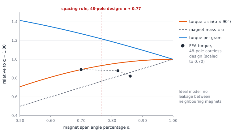
The curves are the ideal model from the table. The black points come from a finite-element (FEA) simulation of a real 48-pole, 54-coil coreless design, run at three spans with the same current:
| Span α | Mean torque | Torque ripple (peak to peak) | Torque per magnet mass |
|---|---|---|---|
| 0.70 | 5.38 Nm | 13.9% | 1.00 |
| 0.82 | 5.30 Nm (−1.4%) | 22.9% | 0.84 |
| 0.86 | 4.96 Nm (−7.8%) | 32.4% | 0.75 |
- Mean torque is the average torque over one electrical period.
- Torque ripple is the difference between the highest and lowest torque in that period, as a percentage of the mean.
- Torque per magnet mass is given relative to the 0.70 rotor.
The ideal model predicts that going from 0.70 to 0.82 adds 8% torque. The simulation shows a small loss instead, and the wider span also brings more ripple and 17% more magnet. Leakage has consumed the whole gain. For this design the spacing rule described below points to α ≈ 0.77, between the two best simulated points.
Back-EMF and top speed
A wider span raises Ke, so the motor generates more back-EMF at a given speed. The drive has to overcome this voltage to push current into the motor, so a higher back-EMF lowers the speed the motor can reach from a given supply voltage. A slightly smaller span is a fine way to win voltage headroom. The number of turns is the coarse adjustment for the same thing.
Influence on Controllability
How easily a drive can control a motor depends on how close the motor's back-EMF is to the waveform the drive expects. The span is one of the strongest levers on that waveform.

- 3rd harmonic (h3). In a star-connected motor with three wires, the 3rd harmonic is identical in all three phases. It cancels in the line-to-line voltage, so the drive never sees it and no current can flow at that frequency. It grows at wider spans. If the winding is delta-connected, h3 is no longer harmless: it drives a current that circulates inside the delta and adds copper loss.
- 5th and 7th harmonics (h5, h7). These reach the drive. With sinusoidal (FOC) currents, they combine into a torque ripple at six times the electrical frequency. They also distort what a sensorless observer measures, and the estimated rotor position then wobbles at the same frequency. Low h5 and h7 give smooth torque and accurate sensorless control.
- Trapezoidal (six-step) drives switch block currents and work best with a flat-topped back-EMF. A wider span (0.85 to 1.00) gives a flatter top.
Span is one of the few parameters that moves h3 in the opposite direction to h5 and h7. In the ideal model, h5 is zero at α = 0.80 and h7 is zero at α ≈ 0.86. A common target for FOC drives, 0.82, sits between these two zeros. A wider span makes the phase waveform look more trapezoidal while making the line-to-line waveform more sinusoidal. Judge a design by its h5 and h7 values, not by how sinusoidal the phase waveform looks.
Why the ideal model is only a starting point
Two filters sit between the block-shaped magnet field and the back-EMF the drive sees:
- The magnetic gap. Higher harmonics fade faster across a gap than the fundamental. The attenuation grows roughly exponentially with harmonic order × gap ÷ pole pitch. Coreless motors have large gaps, so their h5 and h7 are often several times smaller than the chart above suggests.
- The winding. Each pole/slot combination has its own winding factor for every harmonic. Some combinations suppress h5 or h7 strongly, others hardly at all.
That is why, in the 48-pole simulation above, α = 0.70 produced less 6th-harmonic torque ripple than 0.82 (0.71% against 2.03%), although the ideal chart shows the opposite. The true optimum for a given motor has to be found by simulation, by reading h5 and h7 from a back-EMF simulation.
Losses at high speed
Harmonics in the air-gap field also induce eddy currents in the stator conductors, which sit directly in the field of a coreless motor. Eddy loss rises with the square of frequency, so a field rich in high harmonics costs efficiency at high speed. Sharper magnet edges (wider spans with narrow spacing) carry more of these harmonics.
No cogging trade-off
In iron-cored motors, the span is often tuned to cancel cogging torque against the stator teeth. A coreless stator has no teeth and no cogging, so the span is free to be chosen for torque, mass and waveform alone. See Cogging in permanent magnet motors.
The Starting Point: Spacing Equal to the Magnetic Gap
A useful rule of thumb is to make the spacing between magnets as large as the magnetic gap:
ideal spacing = 2 × air gap + stator thickness
The reasoning follows from the leakage picture. Flux leaving a magnet has two routes: across the magnetic gap to the opposite magnet (useful) or sideways across the spacing to the neighbouring magnet (leakage). When both distances are about the same, most of the flux still takes the useful route, because the useful route also has the larger face area. If the spacing is much shorter, leakage climbs quickly. If it is much longer, rotor face is left empty that could have carried useful magnet.
You may also come across a rule that the spacing should equal the magnet thickness. Magnet thickness does matter, because thicker magnets have taller side faces and leak more through the same spacing. But the path the leakage competes with is the magnetic gap, so the magnetic gap is the better yardstick. In the 48-pole design above, the magnet-thickness rule (2.10 mm) would suggest α ≈ 0.87, where the simulation already showed an 8% torque loss. The magnetic-gap rule suggests α ≈ 0.77.
Solving the spacing formula for α gives the span that meets the rule:
αrule = 1 − (2 × air gap + stator thickness) × number of poles ÷ (π × rotor ID)
Treat this as the first value to try, not as the answer.
Deviation from the Ideal Spacing
How far a design is from the rule is expressed as a percentage deviation:
deviation = |actual spacing − ideal spacing| ÷ ideal spacing
A deviation up to about 10% is close enough to count as following the rule. A larger deviation is worth a second look. For example, a design can be described as: "The magnet spacing deviates by 23% from the ideal spacing of 3.88 mm."
Worked example, from the 48-pole design above:
| Input | Value |
|---|---|
| Rotor inner diameter | 252 mm |
| Number of poles | 48 |
| Air gap | 0.75 mm |
| Stator thickness | 2.38 mm |
| Magnet span angle percentage | 0.82 |
- Ideal spacing = 2 × 0.75 + 2.38 = 3.88 mm
- Pole pitch at the inner diameter = π × 252 ÷ 48 = 16.49 mm
- Actual spacing = 16.49 × (1 − 0.82) = 2.97 mm
- Deviation = |2.97 − 3.88| ÷ 3.88 = 23%
- Span that meets the rule = 1 − 3.88 ÷ 16.49 = 0.76
The direction of the deviation tells you what to expect:
- Spacing too small (span too wide, as in the example): expect leakage and diminishing torque per gram. Check that the extra magnet actually buys torque.
- Spacing too large (span too narrow): rotor area is unused. This can be deliberate if you are optimising torque per gram or torque ripple.
Very small spacings are impractical to assemble. Below about 1 mm it is better to let the magnets touch (α = 1.00, spacing 0 mm).
Choosing a Span for Your Goal
There is no single best span. Each goal has its own measure, and the measures pull in different directions:
| Goal | What to measure | Direction | Typical starting range |
|---|---|---|---|
| Maximum torque | Mean torque at the rated current | Wider, until leakage takes over | Around αrule, up to about 0.85 |
| Torque per gram of magnet (cost, weight, rotor inertia) | Mean torque ÷ magnet mass, with a minimum torque target | Narrower | 0.60 – 0.75 |
| Smooth torque (low ripple, low noise) | Torque ripple, 6th harmonic of torque | Simulation decides | 0.65 – 0.80 |
| Sensorless FOC accuracy | Back-EMF h5 and h7 | Simulation decides | 0.75 – 0.85, 0.82 as default |
| Trapezoidal (six-step) drive | Flat-top width of the phase back-EMF (120° electrical is the aim) | Wider | 0.85 – 1.00 |
| Back-EMF headroom / top speed | Line-to-line back-EMF at top speed against DC voltage | Narrower | Reduce in steps of 0.02 |
| High-speed efficiency | Efficiency at top speed (eddy loss in the stator conductors) | Simulation decides, usually narrower | 0.70 – 0.80 |
Torque per gram on its own always prefers the narrowest span, so it only makes sense together with a constraint, for example "the smallest magnet mass that still reaches 8 Nm".
Motor or Generator
The physics is the same in both directions. What changes is who sets the current waveform and what the design is judged on.
Configuring a motor
A motor is driven by an inverter that controls the current shape. Torque, ripple and controllability matter most:
- With FOC, start at 0.82 for sensorless accuracy, or at 0.70 when smooth torque matters more than sensorless accuracy. Confirm with the h5/h7 values and torque ripple from simulation.
- With a six-step drive, start wider (0.85 or more).
- In direct-drive and robotic joints, there is no gearbox to filter ripple, so give torque smoothness a higher weight (Direct-drive motor).
- Keep the back-EMF at top speed below the supply voltage. The span is a fine adjustment, the number of turns is the coarse one.
Configuring a generator
A generator is driven by a prime mover (a turbine, an engine) and delivers its back-EMF to an electrical load. The span now shapes the output voltage itself:
- Generator with an active rectifier (an inverter running in reverse, usually FOC): the same reasoning as for a motor applies. Low h5/h7 keep the current sinusoidal and the torque on the shaft smooth.
- Generator with a passive diode rectifier (common in small wind and hydro): the rectifier draws current in pulses whatever the span, so waveform purity matters less. Priorities become output voltage per rpm (it sets the cut-in speed) and efficiency over the operating range. Generators often run for long hours, so magnet mass and efficiency usually outweigh peak torque.
- Generator feeding AC loads directly: low distortion of the line-to-line voltage matters. Minimise h5 and h7. In star connection, h3 does not appear between the lines.
- Delta-connected generator: keep h3 low, because it circulates inside the delta and heats the winding even with no load connected.
- Small wind turbines must start in light wind. A coreless machine has no cogging torque to overcome, so the span does not need to be compromised for start-up.
Finding the Optimum with a Span Sweep
The rule of thumb and the ideal curves get you close. Leakage, gap filtering and winding harmonics move the true optimum, and only simulation captures all three. A span sweep runs the same motor at several spans while every other parameter stays fixed, then compares the results against your goal.
For each span in the sweep:
- Magnet mass, from the geometry.
- Back-EMF simulation: fundamental (Ke), h3, h5, h7, and line-to-line back-EMF at top speed.
- Current or efficiency simulation at the rated operating point: mean torque, torque ripple, efficiency.
Then pick the span that best meets your goal and its constraints. A typical sweep runs from 0.60 to 0.90 in steps of 0.04, followed by steps of 0.02 around the best point.
The configurator runs such a sweep in one submission, with each span as its own revision. See How to run a magnet span angle sweep for a step-by-step guide with a worked example.
Related Terms
- Air gap: the air gaps on both sides of the stator are part of the magnetic gap that the spacing rule is based on.
- Cogging in permanent magnet motors: why the span is not a cogging tool in a coreless motor.
- Efficiency in permanent magnet BLDC motors: how magnet use and losses add up.
- Direct-drive motor: where torque smoothness matters most.