4. Rotor properties
In a coreless axial-flux motor, the PCB stator sits between two rotor discs that carry permanent magnets. This card sets the geometry and magnet choices that decide the magnetic field in the air gap, and so the torque the motor can make.
Inputs
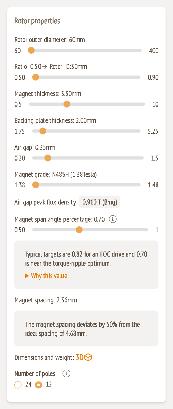
Rotor outer diameter (mm)
Range: 60 – 400 mm
This is the biggest lever you have. Torque rises steeply with diameter, because both the active area and the lever arm grow. If your installation has room, increasing the diameter is usually better than adding stacks.
The outer diameter also sets the minimum air gap (see below), so larger rotors need larger mechanical clearances.
Ratio → Rotor ID (mm)
Range: 0.50 – 0.90
This is the inner-to-outer diameter ratio of the magnet ring: Rotor ID = outer diameter × ratio. Example: 60 mm × 0.50 = 30 mm.
- A lower ratio gives longer magnets (a wider active annulus) and more torque from a given outer diameter.
- A higher ratio gives a narrower ring and less magnet material. It also leaves more room in the middle for a hollow shaft or bearings.
Magnet thickness (mm)
Range: 0.5 – 10 mm
This is the axial thickness of each magnet. Thicker magnets raise the air gap flux density, with diminishing returns, and add magnet weight and cost.
Backing plate thickness (mm)
Range: 0.5 × magnet thickness to 1.5 × magnet thickness
This is the steel back-iron behind the magnets, which closes the magnetic circuit. The allowed range moves with the magnet thickness (in the example: 1.75 – 5.25 mm for 3.5 mm magnets). The analytical flux estimate gets a small boost when the plate is at least about as thick as the magnets (see Air gap peak flux density).
Air gap (mm)
Range: minimum (depends on diameter) – 1.5 mm
This is the mechanical clearance between the magnet surface and the stator on each side. A smaller gap gives more flux and more torque. The minimum is limited by how flat the discs are, how much they deflect, and bearing tolerances, so it grows with the rotor diameter:
| Rotor outer diameter | Minimum air gap |
|---|---|
| below 100 mm | 0.20 mm |
| 100 → 350 mm | rises from 0.20 to 0.90 mm |
| above 350 mm | 1.00 mm |
If you enlarge the rotor and the current air gap falls below the new minimum, the air gap is raised to the minimum automatically.
Magnet grade
Options: N48SH (1.38 T), N50 (1.42 T), N54 (1.45 T), G55 (1.48 T)
The slider steps through the available NdFeB grades. The number in brackets is the remanence Br. A higher grade gives more flux for the same geometry.
Magnet span angle percentage
Range: 0.50 – 1.00
This is the fraction of each pole pitch that is covered by magnet. The value you set is used as it is. It isn't optimised for you.
In the analytical estimates on this page:
- Air gap torque scales with sin(span × 90°), so each step towards 1 adds less torque than the one before.
- Magnet weight scales linearly with span.
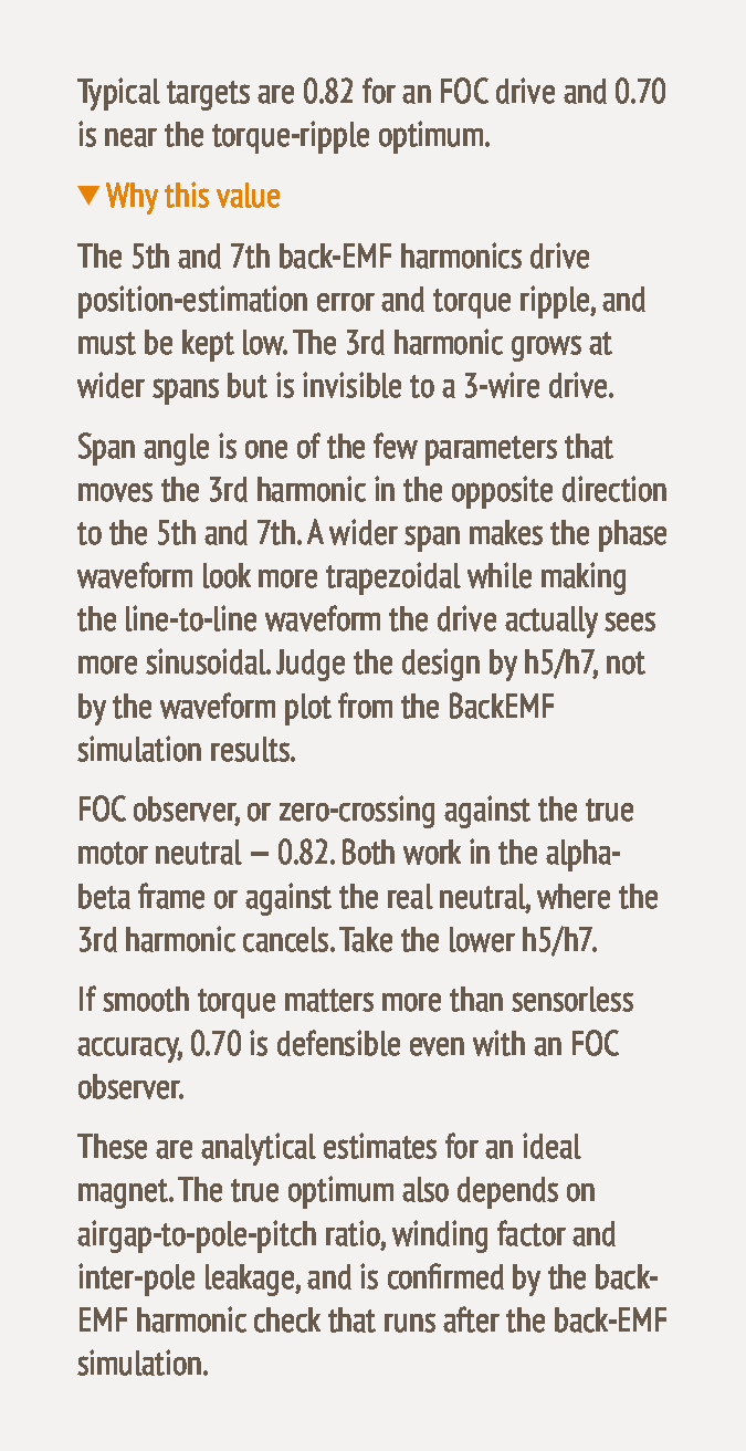
The info box gives typical targets: 0.82 for an FOC drive, and 0.70 near the torque-ripple optimum. Expand Why this value for the reasoning:
In short:
- The 5th and 7th back-EMF harmonics (h5, h7) cause torque ripple and position-estimation error, so they need to be kept low.
- The 3rd harmonic can't be seen by a 3-wire drive.
- Span is one of the few parameters that moves the 3rd harmonic in the opposite direction to the 5th and 7th.
- Judge a span by h5/h7 in the Harmonics tab (guide 8), not by how sinusoidal the phase waveform looks.
Calculated values
Air gap peak flux density (T, Bmg)
This is an analytical estimate of the peak flux density in the air gap:
Bmg = Br × tm / (tm + g + tPCB/2) × k
where tm is magnet thickness, g is the air gap and tPCB is the stator thickness. The factor k depends on how thick the backing plate is compared with the magnet:
- 1.1 if the plate is thinner than 0.9 × tm
- 1.2 if it's up to 1.1 × tm
- 1.3 if it's thicker than that
Example: 1.38 × 3.5 / (3.5 + 0.35 + 1.99) × 1.1 = 0.910 T. Values below 0.6 T turn amber.
Magnet spacing (mm)
This is the gap between neighbouring magnets, measured at the rotor inner diameter:
spacing = π × Rotor ID / number of poles × (1 − span)
Example: π × 30 / 12 × 0.30 = 2.36 mm.
The card compares it with an ideal spacing of 2 × air gap + stator thickness (example: 2 × 0.35 + 3.98 = 4.68 mm) and shows a note if the difference is more than 10 %. Spacing that is too small makes flux leak between neighbouring magnets. If the spacing works out below 1 mm, the magnets are treated as touching (span = 1, spacing = 0 mm).
Dimensions and weight (3D)
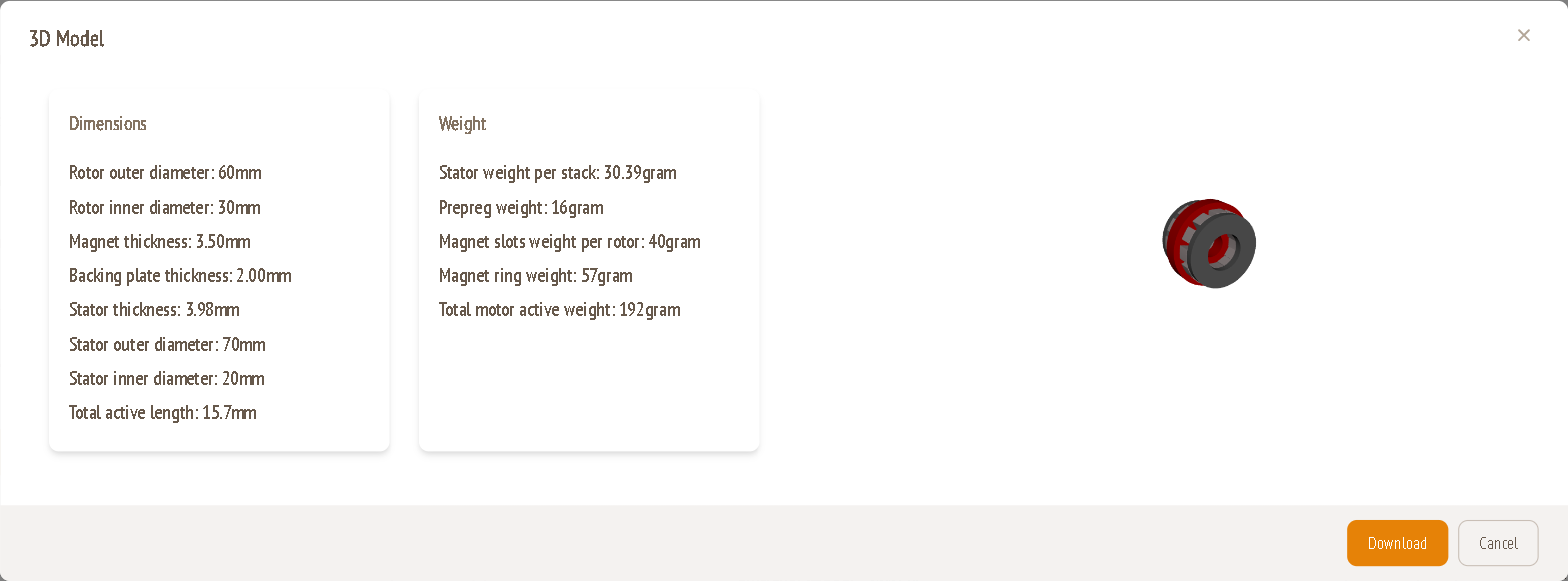
Click 3D to open the 3D model with a dimension and weight summary. Download saves the model.
| Field | Meaning |
|---|---|
| Rotor outer / inner diameter | From the sliders above |
| Magnet and backing plate thickness | From the sliders above |
| Stator thickness, outer and inner diameter | From the stator design |
| Total active length | Axial length of the magnetic assembly: 2 × (magnet + backing plate) + stator thickness + 2 × air gap. Example: 2 × (3.5 + 2.0) + 3.98 + 2 × 0.35 ≈ 15.7 mm. |
| Stator weight per stack, prepreg weight, magnet slots weight per rotor, magnet ring weight | Weight breakdown of the active parts |
| Total motor active weight | Sum of the active parts. This excludes the housing, shaft and bearings. |
Number of poles
Options: 12 or 24
- More poles give more torque and better efficiency at low speed, but a higher electrical frequency, which limits top speed.
- Fewer poles suit high-speed applications.
24 poles is a balanced choice for most applications. The example uses 12 poles because it runs at 6000 RPM with a small rotor.
Tips
- Increase the rotor diameter before you increase magnet thickness or grade. It is the most effective way to add torque.
- Keep the air gap at the minimum allowed for your diameter unless you have a mechanical reason not to.
- Set the span around 0.80 for a first pass. Fine-tune it only after a back-EMF simulation, using the Harmonics tab.