
Axial Flux vs Radial Flux Motors
By Kaan Ozgen · Reviewed
Electric motor selection comes down to two fundamental geometries. In radial flux motors, the design that has dominated the industry for over a century, magnetic flux travels radially outward or inward through a cylindrical air gap. In axial flux motors, flux travels parallel to the rotation axis through a flat disc-shaped gap. Both use permanent magnets and rotating electromagnetic fields to produce torque, but the physical arrangement creates very different performance envelopes across power density, thermal behaviour, form factor, and manufacturing complexity.
For engineers designing weight-critical applications (long-endurance UAVs, eVTOL aircraft, in-wheel EV drives, or compact robotics actuators), these differences carry real design consequences. They determine whether your propulsion system fits the available envelope, meets the power requirement within the weight budget, and sustains high efficiency across the full operating duty cycle.
The Physics of the Two Geometries
Torque in any brushless motor is produced by the force between the stator's current-carrying conductors and the rotor's magnetic field. That force is proportional to the product of the field strength and the current, and it is maximised when the two are perpendicular. The geometry determines how efficiently the motor arranges this interaction across its active volume.
In a radial flux motor, the stator is a cylindrical iron core with slots cut into it to hold the copper windings. The rotor, which carries permanent magnets, surrounds or sits inside this core. The iron is structurally essential: without it, the magnetic reluctance of the air gap would be too high and torque density would collapse. But iron is dense, and it introduces core losses (hysteresis and eddy current losses) that are present at all speeds regardless of load.
In an axial flux motor, the rotor discs face the stator across an axial gap, and the active magnetic interaction covers the full annular disc area rather than a narrow cylindrical shell. This geometry produces a higher torque constant per unit mass. It also enables a coreless stator design: arranging the rotor magnets in a Halbach array (a specific rotating sequence that concentrates flux on one face) removes the need for an iron backing plate behind the magnets. The stator becomes epoxy-embedded copper windings with no iron, removing all core losses from the motor's loss budget.
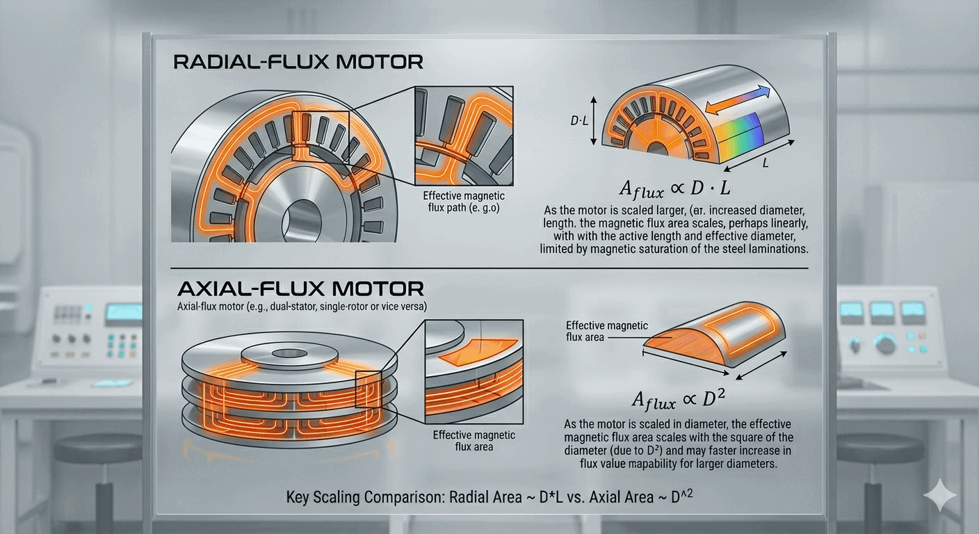
This geometric difference has a direct scaling consequence. In a radial flux motor, the effective magnetic flux area is the surface area of the active cylinder, which scales as diameter × length (D · L): a linear relationship. In an axial flux motor, the flux area is the annular disc surface, which scales with the square of the diameter (D²). Doubling the diameter of a radial motor doubles its flux area; doubling the diameter of an axial motor quadruples it. This is why axial flux motors achieve higher power density as size increases, and why the advantage grows more decisive in the 1 kW and above range.
Side-by-Side Comparison
The table below summarises the key engineering parameters across both topologies. The Axial Flux column is emphasised where it holds a clear advantage for weight- and efficiency-critical applications. Weight and density figures are compared on an active-part mass basis (magnets, copper, and back-iron where present, excluding housing and bearings), continuous rating.
| Parameter | Axial Flux | Radial Flux |
|---|---|---|
| Form factor | Flat disc | Cylinder |
| Power-to-weight ratio | Very high (2–5× radial) | Moderate |
| Torque density | Excellent at low RPM | Good across RPM range |
| Axial length | Very short | Longer |
| Cogging torque | Very low (coreless variants) | Moderate to high |
| Core losses | None (coreless variants) | Present at all speeds |
| Thermal management | Complex (disc geometry) | Straightforward |
| Air gap sensitivity | High: tight tolerances required | More forgiving |
| Scalability | Stack multiple rotors on one shaft | Extend axial length |
| Manufacturing maturity | Growing rapidly | Highly mature |
| Unit cost at volume | Higher (currently) | Lower |
For conversions across unit systems, use our electric motor unit converters for torque, RPM, power, and temperature.
Why Engineers Choose Axial Flux
The advantages of axial flux are most decisive in applications where system weight, packaging space, or partial-load efficiency are primary design constraints. These are the four areas where the topology consistently outperforms radial flux alternatives.
Shorter axial envelope
The disc geometry fits into tight packaging constraints (inside a wheel rim, behind a propeller hub, within a joint actuator, or flush-mounted in a nacelle) without the protruding shaft length of a cylindrical motor. For an eVTOL rotor arm, where every centimetre of axial depth affects airframe structure, or a satellite reaction wheel, where envelope is fixed by launch vehicle constraints, this form factor advantage is decisive. The active magnetic components sit within a volume that is wide and thin rather than narrow and long, which matches a wider range of mechanical integration scenarios.
Higher power-to-weight
The effective torque arm in an axial flux motor (the distance from the shaft to the active air gap) is proportional to the outer radius of the disc. For a given motor volume, this produces a higher torque constant per kilogram of active-part mass than a cylindrical motor of equivalent volume. An axial flux motor producing 500 W continuous may weigh 40–60% less, on an active-part mass basis, than a radial flux motor delivering the same output. On a quadcopter with four motors, saving 100 g per motor saves 400 g total: enough to carry a thermal camera, extend battery capacity, or increase payload. For how printed PCB and DCB stators and housing-free designs push torque per gram further, see lightweight axial flux electric motors, and for how that translates into overall system efficiency, see our efficiency definitions guide.
Direct-drive at low RPM
Because torque in an axial flux motor acts over the full annular disc area rather than a narrow cylindrical shell, the effective torque arm is proportional to the mean radius of the active region, which is large relative to the motor's overall size. This produces a high starting torque constant (Nm/A) per unit mass, enabling direct coupling to propellers, wheels, and joint actuators without intermediate gearboxes. Eliminating the gearbox removes mechanical losses, backlash, lubrication requirements, and a significant source of weight and failure risk. A direct-drive axial flux motor in an EV wheel hub or a drone propeller shaft achieves the same torque output as a geared radial flux motor at a fraction of the total drivetrain mass, with none of the efficiency penalty that gear meshing introduces at partial loads.
Scalable and stackable architecture
Axial flux motors offer a modular scaling path. Increasing outer diameter raises torque at a given speed; adjusting winding turns changes the voltage and current characteristics to match a target ESC or battery voltage. Additional rotor-stator pairs can also be stacked axially on the same shaft, multiplying power output without increasing the motor's footprint. Two stacks double the power; three stacks triple it. The Turncircles motor platform spans from sub-100 W single-stack units for micro UAVs to multi-kilowatt multi-stack configurations for heavy-lift and VTOL cargo applications, all sharing the same tooling, winding process, and magnet sets. This reduces development cost, simplifies certification, and compresses lead times for custom power ratings.
When Radial Flux Still Wins
Radial flux motors remain the right choice for a significant range of applications. Where continuous duty thermal performance, very high rotational speed, or lowest unit cost at volume are the primary requirements, the century of engineering refinement behind radial flux designs gives them a meaningful edge.
Sustained thermal load
The longer cylindrical casing of a radial flux motor presents a larger external surface area relative to its active volume, making convective and conductive heat paths easier to engineer. Standard finned housings, axial fans, and water-jacket cooling are all well-understood for cylindrical geometries. For continuously-loaded industrial applications (pumps, compressors, conveyor drives, HVAC fans), radial flux motors handle sustained 100% duty cycles more predictably. Axial flux motors in high-duty-cycle applications require more careful thermal design, since heat from the stator disc must be conducted out through the housing in a geometry that does not lend itself to simple finning.
Lower manufacturing cost
Decades of optimised tooling, automated lamination stamping, and precision CNC winding have driven radial flux motor costs to commodity levels in the industrial market. The supply chain for lamination steel, standard motor housings, bearings, and matched motor controllers is mature, globally distributed, and highly competitive. At volumes of thousands of units, radial flux motors remain significantly cheaper per kW than axial flux alternatives. For applications where weight and efficiency are secondary to acquisition cost (general-purpose industrial drives, appliances, low-cycle-count actuators), this cost advantage is often decisive.
High-speed operation
Radial flux designs accommodate very high rotational speeds. The cylindrical rotor structure is mechanically robust under centrifugal loading, and the air gap is defined by a simple radial clearance that remains stable as rotor speed increases. Compressor drives, high-speed spindles, turbocharger assist motors, and centrifugal pump impellers operating above 15,000–20,000 RPM are typically better served by radial flux designs. In axial flux motors, maintaining precise disc spacing becomes more challenging at high speed, as centrifugal deflection and bearing dynamics can vary the axial air gap and affect both performance and noise.
Tolerance to air gap variation
The cylindrical air gap of a radial flux motor is maintained by the radial clearance between rotor and stator, a dimension that is relatively insensitive to thermal expansion, bearing wear, or vibration-induced deflection. Axial flux motors require precise control of the disc spacing: the axial air gap is typically 0.5–1.5 mm, and variations on the order of 0.1 mm can measurably affect torque output and increase axial bearing loads. Manufacturing and assembly processes must be held to tighter tolerances, and the rotor assembly must be engineered to minimise thermal growth differentials between the disc and the shaft. For applications in harsh vibration environments or where maintenance standards do not support precision adjustment, this is a genuine disadvantage.
Efficiency Across the Duty Cycle
Motor efficiency varies with speed and load. A motor that achieves 92% efficiency at its rated operating point may drop to 75% at the partial-load cruise conditions that define real-world energy consumption. For radial flux motors, core losses (hysteresis and eddy current losses in the iron stator) are present at all speeds and increase with RPM regardless of whether the motor is under load. At light-load cruise settings, these fixed iron losses account for an outsized share of total input power.
Coreless axial flux motors have no iron in the stator, so core losses are absent. The only loss mechanisms are copper resistance (winding I²R losses, which scale with load current) and bearing friction. The efficiency curve remains flat and high across a wide throttle range. A drone motor that is 94% efficient at full throttle may still be 91% efficient at the 40% throttle typical of cruise, compared to 78–82% for a comparable iron-core motor at the same operating point. Over a one-hour mission, this difference in partial-load efficiency can translate into 15–20% more flight time on an identical battery.
This broad efficiency plateau also means less heat generated per unit of output power across the entire operating range. Less heat means lighter or simpler thermal management, longer winding insulation life, and lower risk of demagnetisation from rotor temperature spikes. These factors contribute to the 20-year service life that well-designed axial flux motors can achieve.
Application Fit at a Glance
The selection logic is straightforward once the primary constraint is identified. If weight, packaging, or partial-load efficiency is the critical variable, axial flux is the correct starting point. If continuous duty thermal performance, very high RPM, or cost minimisation at volume is the driver, radial flux remains competitive. Most applications where engineers evaluate axial flux are ones where the conventional radial flux solution is already straining against weight or size limits.
| Application | Recommended | Primary reason |
|---|---|---|
| Fixed-wing UAV / long-endurance drone | Axial flux | Power-to-weight and flat efficiency curve extend flight time |
| eVTOL / urban air mobility | Axial flux | Disc form integrates into nacelle or rotor hub |
| EV in-wheel drive | Axial flux | Flat profile fits inside wheel rim without gearbox |
| Collaborative robotics joint | Axial flux | High torque density and near-zero cogging for precision control |
| Satellite / space robotics | Axial flux | Mass savings costed at launch price; no core losses in vacuum |
| Industrial pump / compressor | Radial flux | Continuous duty thermal performance and lower cost |
| High-speed spindle (>20,000 RPM) | Radial flux | Air gap stability at centrifugal loads |
| Conveyor / general industrial | Radial flux | Cost, supply chain maturity, serviceability |
Frequently Asked Questions
Can I increase the number of stacks to fit the axial flux motor into my envelope?
To maximise the efficiency of an axial flux motor, use the maximum diameter available in your design envelope: torque scales with the square of the active radius, so diameter is the most powerful lever. Stacking adds power by multiplying active length, but it does not improve the torque constant per unit mass the way diameter does. If your envelope constrains diameter more than axial depth, stacking can help you reach the required power level. If diameter is severely limited, though, a radial flux motor may be a better fit for that installation. The Turncircles configurator lets you explore both dimensions interactively before committing to a design.
Does an axial flux motor always guarantee the highest power-to-weight ratio?
Not always. Motor performance depends on many parameters working together: winding configuration, magnet grade, air gap tolerance, and operating speed all interact. Our experience shows that axial flux motors deliver a power-to-weight advantage (active-part mass basis) over comparable radial flux motors starting from the 1–2 kW range and above; below that threshold, the advantages narrow. Analytics across different motor configurations, power levels, and stack counts are available in the Turncircles Configurator App, where you can compare simulated performance data for your specific requirements.
Specify an axial flux motor for your application
Use the Turncircles configurator to set your torque, speed, and power requirements and get a simulation-backed motor specification, in minutes.
Configure your motor