
Axial Flux Permanent Magnet Motors (AFPM): BLDC, 3-Phase and Everything in Between
By the Turncircles engineering team · Published
Axial flux permanent magnet motors go by many names: AFPM, axial BLDC, axial electric motor, pancake motor. Underneath the vocabulary there is one idea: put the magnets and the windings on flat discs and let the flux cross the air gap along the shaft.
This guide sorts the names out, shows the main topologies, explains how a BLDC or PMSM drive treats the same machine, and says where this design fits and where it does not.
Configure an axial flux PM motor Read the axial flux motor guide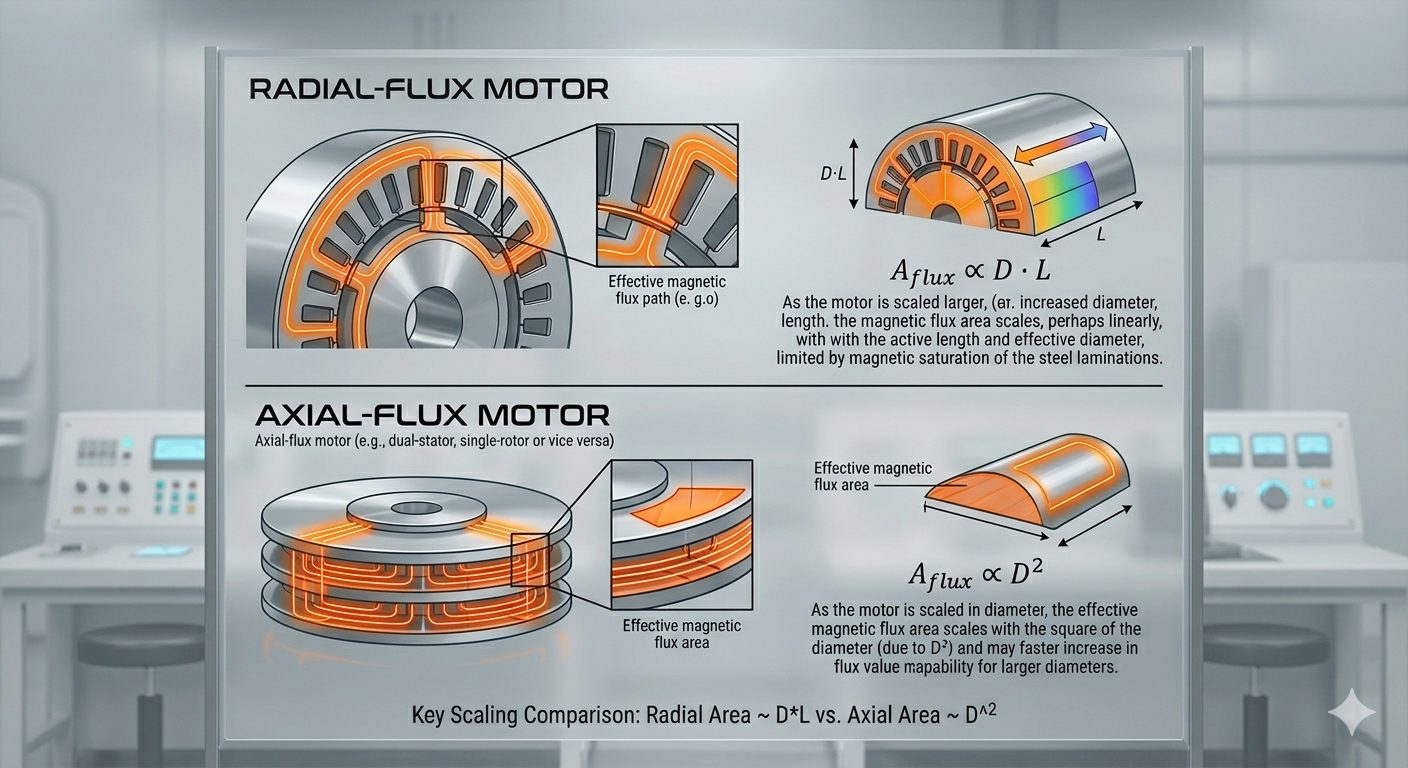
AFPM, Axial Flux BLDC, Axial Electric Motor: Same Animal, Many Names
The search results for this machine are a small zoo. "AFPM motor" is the academic abbreviation for axial flux permanent magnet motor. "Axial flux BLDC" is what you say when you care about how it is driven. "Axial motor" and "axial electric motor" are what people type at 11 pm. And "flux motor" is, strictly, every motor ever built, since flux is how torque happens, and has nothing to do with capacitors that travel in time.
They all describe the same thing: a motor whose magnets sit on flat discs, whose windings sit on a flat stator between or beside them, and whose magnetic flux crosses the air gap parallel to the shaft. If you want the general picture first, start with the axial flux motor guide.
Topologies: Where the Stator and Rotors Sit
| Topology | Layout | Where it shows up |
|---|---|---|
| Single rotor, single stator | One magnet disc facing one stator | Simple, light, but the magnets pull the disc towards the stator |
| Double rotor, single stator | Stator between two magnet discs | Common for coreless and PCB-stator designs. The net axial force on the stator largely cancels; the rotors attract each other |
| Single rotor, double stator | Rotor between two stators | Higher torque from the same magnet, more complex winding and cooling |
| Multi-stage | Several rotor-stator pairs on one shaft | Torque and power scale with the number of stages |
Our motors use the double rotor, single stator layout with a printed stator, and scale by adding stacks, the multi-stage idea. The stator between two rotors matters for a practical reason: the two rotors attract each other strongly, and the structure has to carry that force, while the stator sits in the field between them without being pulled to one side.
BLDC or PMSM? It Is the Same Motor Driven Differently
A brushless DC motor and a permanent magnet synchronous motor are both a magnet rotor chasing a rotating field made by three phase windings. The difference is in how the controller drives them. A BLDC drive switches current in six steps based on rotor position, and the back-EMF is ideally trapezoidal. A PMSM drive feeds sinusoidal currents (often with field-oriented control) to a machine whose back-EMF is ideally sinusoidal. Many motors can run either way, with trade-offs in smoothness, efficiency and drive cost.
In practice you choose the drive for your application. Sensor-based or sensorless, six-step or field-oriented, the motor needs rotor position information to commutate. Which drive suits which application is covered in our BLDC actuators vs stepper motors definition.
Three Phases, Poles and Coils
A three-phase axial flux motor has its coils divided into three groups, with the phase currents shifted by 120 electrical degrees so that the field rotates. The number of magnet poles and the number of coils decide how the machine behaves. A 12-pole, 9-coil combination, for example, repeats every 120 degrees, gives a high winding factor and, in a coreless stator, no slot cogging at all. Other combinations trade torque smoothness, harmonic content and winding complexity against each other.
The winding calculator lets you see winding factors for different pole and slot combinations. The magnet selector shows how magnet choices change flux.
Coreless: No Iron in the Stator
Many axial flux permanent magnet motors have iron in the stator, with coils wound around teeth. Ours does not. The coils are traces on a printed stator, so there is no iron to saturate, heat or attract the magnets, and none of the core losses that go with it. That is why efficiency stays high across a wide speed range and why the motor has no slot cogging. The coreless axial flux motor page explains the trade-offs honestly, including why a coreless design has a larger effective air gap and needs stronger magnets to bridge it.
Where AFPM Motors Fit
- Weight-critical machines: drones, aircraft, robots. See aerospace electric motor design.
- Wheels and traction: direct drive hub motors. See axial flux hub motors.
- Flat spaces: pumps, fans, gimbals and anything where length is limited.
- Efficiency-sensitive drives: where the motor runs many hours a year.
And where they do not: very cheap volume applications where a catalogue radial motor with a gearbox already does the job. See the axial flux vs radial flux comparison for a balanced view.
Frequently Asked Questions
What is an axial flux permanent magnet (AFPM) motor?
A motor with permanent magnets on flat rotor discs and windings on a flat stator, where the magnetic flux crosses the air gap parallel to the shaft. The disc shape gives high torque for its weight and a short axial length.
What is the difference between an axial flux BLDC motor and a PMSM?
The machines are similar. The difference is the drive: a BLDC drive commutates in six steps and expects a trapezoidal back-EMF, while a PMSM drive uses sinusoidal currents. The same axial flux motor can often be run either way.
Is an axial flux motor AC or DC?
Both, in different places. It is supplied from a DC source through a drive that creates three alternating phase currents inside the motor. It has no brushes.
What is a 3 phase axial flux motor?
An axial flux motor whose windings are arranged in three groups fed by phase currents 120 electrical degrees apart, creating a rotating magnetic field that drags the rotor around.
Why choose a coreless axial flux motor?
No iron in the stator means no core losses, no slot cogging and less weight. The cost is a larger effective air gap that demands stronger magnets, and a thermal design that has to take heat out of copper and substrate rather than iron. See the coreless axial flux motor page.
Configure an axial flux permanent magnet motor
Pick torque, speed and voltage, and see the simulated motor.
Configure your motor Talk to an engineer