
Axial Flux Motor: How It Works and Where It Fits
By Kaan Ozgen · Published
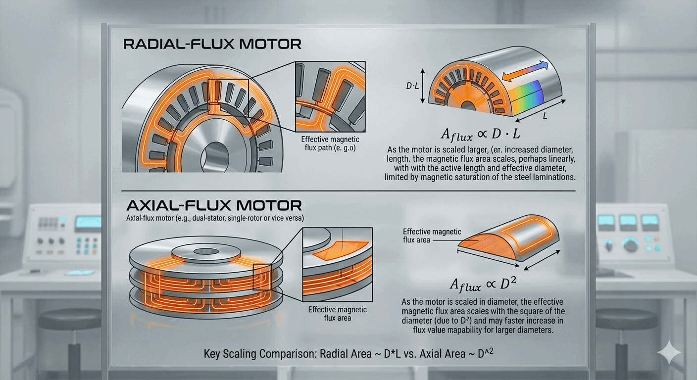
An axial flux motor is a permanent magnet machine in which the magnetic flux runs parallel to the shaft. The stator and rotor are discs that face each other across a flat air gap. Because torque comes from the area and the radius of that gap, the design gives high torque in a short, wide package. The trade-offs are the axial force between the discs, tighter mechanical tolerances, and thermal paths that need checking. It fits best where diameter is available and length is not.
This page explains the layout, works through the torque scaling with real numbers, and ends with a decision guide and the three questions to ask of any axial flux datasheet.
Table of contents
- 1. What the Name Means
- 2. How the Layout Works
- 3. Worked Example: How Diameter Changes Torque
- 4. Worked Example: When Short and Wide Wins
- 5. Where Axial Flux Gains
- 6. Where Axial Flux Has Trade-offs
- 7. Common Layouts
- 8. Comparison with Radial Flux
- 9. Where Axial Flux Is Used
- 10. How to Decide Whether Axial Flux Fits
- 11. Reading an Axial Flux Datasheet
- 12. Glossary
- 13. Frequently asked questions
1. What the Name Means
"Axial" describes the direction of the magnetic flux, not the shape of the housing. In a radial flux motor, flux crosses a cylindrical air gap, moving outward from the shaft. In an axial flux motor, flux crosses a flat air gap, moving parallel to the shaft. Both can use permanent magnets, both can be driven as brushless DC or as synchronous machines, and both can be built in a wide range of sizes. What differs is the geometry of the gap, and that geometry decides where the torque comes from and which envelope each design suits.
The flat shape that usually comes with axial flux is a consequence, not the definition. A motor can be flat and still be radial flux: most gimbal and drone outrunners are short radial machines. That distinction is covered on the pancake motor page.
2. How the Layout Works
An axial flux machine has three main parts:
- Rotor discs carry the permanent magnets, usually on a backing plate that also closes the magnetic circuit.
- Stator carries the windings. It can have an iron core, or no core at all (coreless).
- Air gap is the flat annulus between the rotor and stator faces. Its area and radius set how much torque the motor can make.
In the simplest model, torque comes from the tangential force per unit area in the gap, the shear stress σ, acting at a radius. Integrating that force over a disc face with inner radius Ri and outer radius Ro gives the standard expression:
T = 2π⁄3 · σ · (Ro3 − Ri3)
This is a textbook model for one active gap face at uniform shear stress. A machine with two gaps (one stator between two rotors, or the reverse) has two faces and roughly twice the torque at the same σ. Real designs lose some of this to end windings, saturation and leakage, so a simulation is always needed before a build. The model is useful for one thing: seeing how size changes torque.
3. Worked Example: How Diameter Changes Torque
Take a single gap face with Ro = 50 mm and Ri = 25 mm, a common inner-to-outer ratio of 0.5, and an illustrative shear stress of σ = 15 kPa for a small, naturally cooled machine:
T = 2.094 × 15,000 Pa × (0.0503 − 0.0253) m3 ≈ 3.4 Nm
Double the outer radius to 100 mm, keep the ratio at 0.5 and keep σ the same:
(2Ro)3 ÷ Ro3 = 8 → T ≈ 27.5 Nm
Doubling the diameter multiplies torque by about eight in this model. A radial motor of fixed active length scales with the square of the gap diameter instead, so doubling its diameter roughly quadruples its torque. This cube law is why axial flux gets attention whenever the envelope is wide.
Two cautions. First, the cube law only holds at a fixed Ri/Ro ratio and a fixed shear stress. Shear stress is set by how much current the winding can carry and how well the heat leaves, and a larger motor does not keep the same σ automatically. Second, at a fixed shear stress a smaller inner radius always gives more torque; the often-quoted optimum ratio of about 1/√3 ≈ 0.58 appears only once the limited room for copper at the inner radius is included (Gieras, Wang & Kamper, Axial Flux Permanent Magnet Brushless Machines, 2nd ed., Springer, 2008). Use the model to compare options, not to predict a final torque.
4. Worked Example: When Short and Wide Wins
The same model shows where axial flux pays off. A radial gap at radius r with active length L produces T = 2π · r2 · L · σ. Put the radial gap at the same 50 mm radius and the same 15 kPa as the example above, and ask how long it must be to match the axial machine:
| Axial machine | Axial torque | Radial active length for the same torque |
|---|---|---|
| One gap face, Ri = 25 mm | 3.4 Nm | about 15 mm |
| Two gap faces (double-sided) | 6.9 Nm | about 29 mm |
Below those lengths, the flat gap gives more torque for the same diameter; above them, the radial gap does. A real radial motor also needs end windings and bearings beyond its active length, which moves the crossover further in favour of axial flux in very short envelopes. This is the quantitative version of "short and wide": axial flux wins when length is the scarce dimension, not in general.
5. Where Axial Flux Gains
- Torque for a given length. A short axial package can deliver the torque of a longer radial machine, if the diameter is available (see the example above).
- Coreless construction. With no iron in the stator, there is no stator core loss and no cogging from slots. The trade-offs are a larger magnetic gap, more magnet material, and eddy-current loss in the conductors themselves at high electrical frequency. Turncircles builds its coreless stators as PCB or DCB windings.
- Stacking. Adding rotor and stator stages raises torque without changing the outer diameter, and lets one set of parts cover a range of torques.
- Thin rotor. The magnets sit on a flat disc, so the rotor adds little axial length and can be integrated into a hub or joint.
6. Where Axial Flux Has Trade-offs
- Axial force. Magnets pull rotor and stator together. A single-sided machine with an iron stator has a large one-way force that the bearings, housing and mounting must carry. In a two-rotor layout the forces on the stator largely cancel, but the two rotor discs are still pulled towards each other, so the rotor structure has to carry that load instead.
- Air-gap tolerance. A flat gap is sensitive to misalignment, disc flatness and bearing play. It has to stay within tolerance under load and temperature change.
- Iron stators are harder to make. Laminations for an axial gap cannot simply be stamped and stacked as in a radial motor; they are wound as a spiral tape core or made from soft magnetic composite. Slotted iron stators also bring cogging and core loss, as in radial machines.
- Heat leaves through a different surface. Depending on the housing, a flat machine may have less cooling surface near the winding than a long radial one. Check the thermal design for the duty cycle, not only the peak torque.
- Manufacturing maturity. Each disc has to be flat and aligned, and the supply chain at volume is younger than for radial motors.
7. Common Layouts
| Layout | Description | Typical use | Watch for |
|---|---|---|---|
| Single-sided | One rotor, one stator | Simple builds, lower torque | One-way axial force on bearings |
| Double-sided, two rotors | Two rotor discs around one stator | Higher torque in the same diameter; common with coreless stators | Rotor discs attract each other; balance of the two gaps |
| Double-sided, two stators | Two stators around one rotor | Iron-cored designs with a thin central rotor | Rotor stiffness and retention |
| Multi-stage | Several rotor and stator pairs on one shaft | Scalable torque in a fixed diameter | Stack tolerance, heat in the middle stages |
| Coreless stator | Stator without iron | Low ripple, no core loss, low mass | Larger magnetic gap, conductor eddy losses |
| Iron-cored stator | Tape-wound or composite core with slots | Higher torque per magnet volume | Cogging, core loss, harder manufacture |
8. Comparison with Radial Flux
| Factor | Axial flux | Radial flux |
|---|---|---|
| Shape | Short and wide | Long and narrow |
| Torque scales with | Outer radius cubed (fixed ratio, fixed σ) | Gap diameter squared × active length |
| Axial force | Significant; carried by bearings or rotor structure | Small in normal designs |
| High speed | Possible; large rotor discs need retention | Usually easier to support |
| Manufacturing maturity | Younger at volume | Mature, many suppliers |
| Best fit | Diameter available, length limited | Length available, high speed, high volume |
The axial flux vs radial flux comparison covers the trade-offs in more depth, and the torque and power density guide explains why the geometry matters for Nm/kg.
9. Where Axial Flux Is Used
Drones and eVTOL aircraft, where mass and length both matter. Robot joints and actuators, where a short hub suits the envelope. Light electric vehicles and in-wheel drives. Development rigs where a flat machine is easier to package.
For applications where mass is the hard limit, see custom lightweight axial flux motors, which covers naked and wet motors that remove the housing weight.
10. How to Decide Whether Axial Flux Fits
Work through these questions in order:
- Is the envelope wide and short? If the space along the shaft is tight but the diameter is available, axial flux is worth a look. If the envelope is long and narrow, radial is usually simpler.
- Is the speed high? At high speed, large rotor discs need strong magnet retention and the gap needs care. Check the rotor design with the supplier before committing.
- Is the mass limit hard? Coreless axial flux options help. Check whether quoted mass figures include housing and bearings.
- Is the thermal duty continuous? Continuous high torque is the hardest case for a flat machine. Ask for the thermal analysis at your duty cycle.
- Will the volume be high? At high volume, radial designs have a mature supply chain. For axial flux, the choice of supplier matters more; the manufacturers guide shows how to compare them.
If the answers point toward axial flux, the next step is a design study. The custom motor design process shows what the study involves and what it needs from you.
11. Reading an Axial Flux Datasheet
Three questions decide whether two datasheets can be compared:
- Torque basis: continuous or peak, and for how long the peak holds.
- Mass basis: active parts (stator and rotor) or the complete motor with housing and bearings.
- Data basis: measured on a test bench, or taken from a simulation.
A figure such as "24 Nm per stack" is only useful once these three are stated. The torque and power density guide explains each basis and states the one Turncircles uses.
12. Glossary
- Air gap: the space between rotor and stator where torque is produced.
- Shear stress (σ): tangential force per unit area in the gap; the product of electric and magnetic loading, limited mainly by cooling.
- Coreless: a stator with no iron core; the winding is self-supporting or printed.
- Cogging: torque ripple at zero current caused by magnets interacting with stator slots or iron.
- Torque ripple: variation of torque with rotor position under load.
- Stack: one rotor and stator pair. Stacks can be added to raise torque.
13. Frequently Asked Questions
What is an axial flux motor?
A permanent magnet motor in which the magnetic flux crosses a flat air gap parallel to the shaft. Rotor and stator are discs facing each other, which gives high torque in a short, wide package.
Is an axial flux motor better than a radial one?
It depends on the envelope. Axial flux gives more torque per unit length when the diameter is available. Radial flux suits long envelopes, very high speeds and high-volume supply.
Does an axial flux motor need a gearbox?
Not necessarily. Many axial flux motors run direct drive because they make high torque at low speed. Check whether your speed requirement works without a gearbox before adding one.
Why are axial flux motors harder to build?
The flat air gap needs tight flatness and alignment, the magnetic pull between discs loads the bearings or rotor structure, and iron stators for an axial gap need tape-wound or composite cores instead of stamped laminations.
What is the cube law in axial flux motors?
In the simple shear-stress model, torque scales with the cube of the outer radius at a fixed inner-to-outer ratio and fixed shear stress, so doubling the diameter multiplies torque by about eight. Real designs differ, so use it only to compare options.
Are coreless axial flux motors less efficient?
Not automatically. Coreless designs remove stator core loss and cogging, but the larger magnetic gap and eddy losses in the conductors have to be checked against an iron-cored alternative for the same duty cycle.
How do I compare axial flux suppliers?
Ask each one for continuous and peak torque, the mass basis, the data basis, the cooling method and the lead time, and put the answers in one table. The manufacturers guide has a template.
Can I get a custom axial flux motor?
Yes. Enter your torque, speed, voltage and envelope in the Turncircles configurator to get an analytical result and an indicative price, then run a simulation before any build.
Configure an axial flux motor
Set your torque, speed, voltage and envelope, and get an analytical result and an indicative price in minutes. Run a simulation before you commit to a build.
Configure your motor