
Coreless Axial Flux Motor: The Ironless Stator Explained
By Dr. Erik Nordlund · Reviewed
A coreless (or ironless) stator holds its copper windings in a non-magnetic matrix (epoxy, or a rigid PCB or DCB substrate) instead of laminated iron teeth. In a coreless axial flux motor, that means the disc between the two rotor magnet plates carries no iron at all: no slots, no laminations, nothing for the rotor's field to grip or resist. That single design choice removes an entire category of losses from the motor, at the cost of others.
This guide states the trade-offs plainly: where coreless wins, and where it doesn't, matters more than picking a side.
What a Coreless Stator Is
A conventional stator is built around a stack of laminated iron sheets, cut or punched into teeth and slots. The copper winding sits in those slots, and the iron carries the magnetic flux between them. It's the reason a slotted motor can produce high torque from a compact volume. A coreless stator removes that iron entirely. The winding is self-supporting, held in shape by epoxy potting or, increasingly, printed directly as copper traces on a rigid PCB or DCB substrate. Because there's no iron, the whole assembly is sometimes called an air-core stator motor: the winding sits in what is otherwise just the air gap.
The two designs are easiest to picture side by side: a slotted iron-core stator is a toothed ring with copper wound into each slot; a coreless stator is a flat, thin disc of copper conductors with nothing solid between them but insulation and potting compound. In an axial flux motor, that disc sits directly in the gap between two rotor plates, so a coreless stator design and a thin-disc rotor pair naturally.
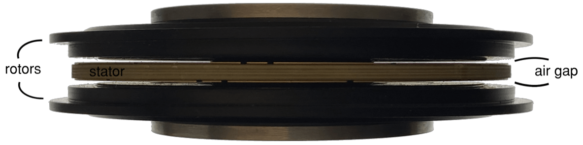
A coreless stator disc sits directly in the axial air gap between the two rotor plates. There is no iron for it to be wound around.
Why Remove the Iron
Iron teeth do real work in a slotted stator: they concentrate flux and lower the reluctance of the magnetic circuit, which is exactly what lets a slotted motor be compact. But that iron also carries a fixed cost, present at every operating point, not just the demanding ones.
- Hysteresis and eddy-current losses. Every time the iron's magnetic domains flip with the passing rotor field, they dissipate energy as heat. These core losses scale with frequency and exist even at no load, purely because the rotor is turning.
- Cogging torque. The iron teeth attract the rotor magnets as they pass, creating a periodic detent force that resists smooth rotation, most noticeably at low speed.
- Saturation limits. Iron can only carry so much flux before it saturates and stops contributing proportionally, which caps how hard the magnetic circuit can be driven.
- Mass. Iron is dense. In a motor where every gram counts, the stator core is rarely the lightest way to spend that mass budget.
Remove the iron and all four effects go with it, because the mechanism that causes them no longer exists in the stator.
What You Gain
Cogging Torque Elimination
With no iron teeth for the magnets to attract, reluctance-based cogging torque is eliminated, not just reduced. This matters most at low speed and at standstill, where cogging is otherwise most noticeable as jerky, uneven rotation. For applications that need to start and hold position smoothly (precision actuators, gimbals, direct-drive joints), this is often the single most valuable property of going coreless.
The same absence of iron also means true zero core loss: no hysteresis, no eddy-current loss in the stator, at any speed. Combined with the very low rotor and stator mass of a thin coreless disc, this typically produces high efficiency at part load and high speed, exactly the operating region where a conventional slotted motor's core losses cut most into efficiency. Rotor inertia drops too, which improves both torque density per kilogram and the motor's dynamic response. The result, in normal operation, is a smoother, quieter motor: no reluctance torque ripple, and no core-loss buzz superimposed on the winding's electromagnetic noise.
What You Give Up
A Larger Effective Air Gap
Without iron to concentrate flux, the magnetic circuit sees a much larger effective air gap. The winding thickness itself is now part of the gap the flux has to cross. Reaching useful flux density across that gap needs stronger magnets, almost always arranged as a Halbach array or in a dual-rotor configuration that sandwiches the coreless stator between two magnet plates facing each other. Without it, a coreless design can't produce competitive torque.
Lower Inductance, Higher Ripple
A coreless winding has lower self-inductance than an iron-backed one. There's no high-permeability path to concentrate the winding's own field. Lower inductance means current ripple rises for a given PWM switching frequency, which pushes the design toward faster switching or a higher PWM frequency to keep ripple, and the losses it causes, under control.
AC Copper Losses in Coreless Windings
With no iron to shield them, the windings sit directly in the full time-varying field, and skin and proximity effect losses become significant, often the dominant loss term at high electrical frequency. This trade-off is easy to underestimate: a coreless motor can win on core loss and still lose the efficiency argument overall if the conductor geometry isn't designed for AC operation from the start.
No Iron Path for Heat
A slotted stator's iron doubles as a heat-conduction path to the housing. A coreless stator has none of that; the thermal design rests entirely on the potting compound and the end windings, which makes conductor placement, potting material choice, and, where used, DCB ceramic substrates part of the electromagnetic design.
How the Losses Actually Shift
Coreless relocates loss rather than eliminating it. The table below compares where each loss mechanism sits between a coreless and a slotted stator, not how large it is in absolute terms; the actual numbers depend entirely on the specific design.
| Loss mechanism | Slotted iron-core stator | Coreless stator |
|---|---|---|
| Core loss (hysteresis, eddy current in iron) | Present at all speeds, scales with frequency | None: no iron to carry it |
| AC copper loss (skin and proximity effect) | Partially shielded by the iron teeth | Higher: windings sit fully in the field; needs litz wire or fine conductor geometry to control |
| Cogging torque | Present, most noticeable at low speed | None: no iron teeth to attract |
| Windage | Depends on rotor/stator geometry, broadly similar | Depends on rotor/stator geometry, broadly similar |
The practical design levers on the coreless side of that table are conductor geometry and, for the AC copper loss row specifically, litz wire: many thin, individually insulated strands woven so each carries a more even share of the current, which is standard practice for winding a high-frequency axial flux stator disc.
Why Turncircles Chose Coreless
The case for coreless is stronger in an axial flux motor than in a radial flux motor, and the reason is geometric. Torque in an axial flux motor acts at a larger mean radius than in an equivalent radial motor, which is the source of its torque advantage in the first place. But keep an iron core in both topologies, and the axial motor pays a larger penalty for it: higher torque ripple, because the same magnet-to-tooth attraction acts over a larger active area, and higher eddy-current losses, because that larger flux area is exactly what generates more induced current in the iron.
The penalty for retaining iron is topology-dependent, and it's worst exactly where axial flux's torque advantage is best. Going coreless removes the losses and ripple that the axial topology amplifies, while keeping the torque advantage the topology provides in the first place, which lets Turncircles exploit the topology fully. That's the reasoning behind Turncircles' coreless stators, built as printed PCB or DCB discs; see how PCB and DCB stators translate into torque per gram for the mechanical side of that design.
Where Coreless Is the Right Call
Coreless motors earn their keep where zero cogging torque, low mass, and good efficiency at part load and high speed matter more than raw torque per unit cost:
- Drones and eVTOL. Mass and part-load efficiency dominate the propulsion budget; cogging-free operation also helps flight-control smoothness.
- Robotics and direct-drive joints. Zero cogging torque means precise, backlash-free motion without a gearbox masking it.
- In-wheel traction motors. Low rotor mass reduces unsprung weight, and the flat disc form factor fits inside a wheel rim.
- Generators at variable speed. No core loss at any speed keeps generation efficiency high across a wide operating range.
- Precision positioning. Smooth, ripple-free torque is worth more than peak torque density.
Coreless is the wrong call for low-speed, high-torque applications on a cost-driven magnet budget: the stronger magnets a coreless design needs to bridge its larger air gap are expensive, and a well-designed slotted motor's iron can deliver comparable low-speed torque for less magnet material. If cogging and core loss aren't the binding constraint, a slotted design is often the more economical choice.
Designing One: Why Coreless Motors Need FEM Simulation
A coreless stator is harder to design correctly than its simplicity suggests, and analytical formulas fall short in ways that matter. Flux paths in a coreless axial flux motor are three-dimensional: there's no iron to constrain them to a convenient 2D cross-section, so a 2D model misses real fringing and edge effects at the winding's inner and outer radius. AC losses have to be evaluated per individual strand, not as a lumped copper-loss term, since skin and proximity effect depend on each conductor's position within the winding. And the magnets and any retaining structure see transient eddy currents during switching events that a static or 2D analysis doesn't capture.
That combination is why 3D finite-element simulation, not 2D or analytical modelling, is the baseline requirement for a coreless design that will perform as predicted, and a large part of why designing a motor around its application means simulating it.
Frequently Asked Questions
What is a coreless stator?
A coreless (or ironless) stator holds its copper windings in a non-magnetic matrix (epoxy, or a rigid PCB or DCB substrate) instead of laminated iron teeth. There is no ferromagnetic core for the rotor's field to act against, only the winding itself sitting in the air gap.
Does a coreless motor have cogging torque?
No reluctance-based cogging. Cogging torque comes from the rotor magnets attracting the iron teeth of a slotted stator as they pass; a coreless stator has no iron teeth to attract, so that mechanism is removed entirely, not just reduced.
Are coreless motors more efficient?
At part load and high speed, usually yes, because core losses (hysteresis and eddy current losses in the iron) don't exist to subtract from output. At high current or low speed, AC copper losses in the windings can offset some of that gain, so the honest answer is application-dependent, not universal.
What are the disadvantages of a coreless stator?
A larger effective air gap that demands stronger magnets, usually in a Halbach array; lower winding inductance that raises current ripple and pushes switching frequency up; AC copper losses (skin and proximity effect) that become the dominant loss term at high frequency; and no iron path to conduct heat away, so thermal design falls entirely on the potting compound and end windings.
Turncircles builds coreless axial flux motors as printed PCB and DCB stator discs, designed and verified with 3D FEM simulation rather than analytical shortcuts, so the trade-offs above are engineered for rather than discovered in testing. The same coreless stator suits both sealed and canned wet-rotor construction, if your application needs to run in fluid rather than just tolerate it. See how turns, layers and traces are set for a PCB stator in the Configurator Guide's Stator properties guide.
Specify a coreless axial flux motor for your application
Use the Turncircles configurator to set your torque, speed, and power requirements and get a simulation-backed motor specification in minutes.
Configure your motor